9-12 Structure and Assembly/Disassembly
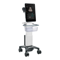
2. Pull the TGC caps upwards.
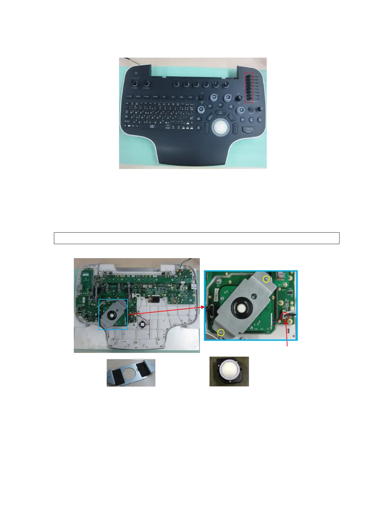
9.3.6.4 Trackball
1.
Refer to 9.3.6 Control Panel Assembly for details.
2. Wear the anti-electrostatic glove. Place the control panel assembly on the tool. Pull the signal
wire (009-004569-00) of the trackball out of the trackball assembly and the control panel board.
Unscrew 2 M3 X 8 panhead screws from the trackball bracket with cross screwdriver (M3, M4).
Remove the trackball bracket, and take the trackball out (2 inches USB port).
If there is no tool available, place the book besides the control panel assembly.
9.3.6.5 Trackball Key Board PCBA/Large, Small Fan-shaped Buttons
1. Refer to 9.3.6 Control Panel Assembly and 9.3.6.4 Trackball for details.
2. Wear the anti-electrostatic glove. Unplug one signal control wire (009-004568-00) from the
trackball board. Unscrew 4 M3 X 8 small panhead screws with screwdriver (M3, M4) to remove
the trackball button board PCBA (with silicon button).
Signal wire of
the trackball
Trackball 2 inches USB port
cap (8)
 Loading...