Do you have a question about the Mindray TEX20 and is the answer not in the manual?
Details the version history of the service manual, subject to updates without prior notice.
Outlines Mindray's ownership of intellectual property rights for the product and manual.
Defines the manual's intended audience as technically qualified personnel for service procedures.
Specifies conditions under which Mindray is not responsible for product safety, reliability, or performance.
Details Mindray's warranty for system components and exclusions, including consumables.
Provides contact information for Mindray's service department.
Explains symbols and conventions used for menu items, buttons, and operations in the manual.
Provides safety guidelines for system use and describes safety labels and symbols.
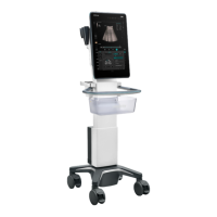
Provides an overview of the product and its intended use for clinical ultrasound diagnosis.
Details the physical, electrical, environmental, and display specifications of the system.
Explains the system's hardware architecture and functional principles.
Covers environmental, power supply, EMI, space, network, and other requirements for site setup.
Provides instructions for unpacking the device, checking the package, and identifying contents.
Details procedures for transporting the main unit in a car or elevator.
Guides through connecting external power and assembling major system components.
Explains how to adjust the system, specifically the display position and angle.
Provides instructions for connecting various peripherals like footswitches and printers.
Details the process of starting the system and configuring various software settings.
Covers network configuration, including Wi-Fi, iStorage, Medtouch, remote maintenance, and eGateway.
Explains how to configure DICOM and HL7 services for data transfer.
Describes how to manage user access, add/delete users, modify passwords, and configure LDAP.
Details disk encryption/data clearing and antivirus settings for system security.
Provides a brief overview of the recommended check processes covered in this chapter.
Details checks for running status, power-on, and operating environment conditions.
Outlines the process and items for performing routine system checks.
Describes procedures and items for checking system functions across various imaging modes.
Details the process and items for testing system performance metrics like resolution and depth.
Covers general care, tools, consumables, routine maintenance items, and system cleaning procedures.
Details procedures for viewing system information, logging in as service user, and software recovery.
Explains how to obtain and upgrade the operating system and application software.
Provides instructions on upgrading optional software functions.
Lists hardware accessories and methods for upgrading them.
Covers personnel requirements, preparation, and system structure before FRU replacement.
Details the general information, disassembly, assembly, and verification for the display unit.
Provides information and steps for disassembling and assembling the main unit front cover.
Details the main board's functions, disassembly, assembly, and verification procedures.
Explains the general information and replacement steps for the dual fan assembly.
Provides general information and procedures for disassembling and assembling the main unit back cover.
Covers system indicators, status indicators, startup process, and battery health.
Addresses errors related to battery, voltage, temperature, and fan alarms with potential causes and solutions.
Provides solutions for power-on, system startup, image, probe recognition, and display errors.
Illustrates phantom usage, including target groups and simulated lesions for testing.
Provides a diagram showing the internal electrical connections of the TEX series product.
Details various self-test items, including failure analysis and troubleshooting suggestions.
Covers electrical safety inspection procedures for power cords, device shells, labeling, and ground impedance.
| Display Type | LED |
|---|---|
| Touch Screen | Yes |
| Battery Life | Up to 4 hours |
| Probe Connectors | 2 |
| Type | Ultrasound System |
| Imaging/Scan Modes | B-mode, M-mode, Doppler |
| Operating Modes | Cardiac, Vascular, Abdominal, Obstetrics, Gynecology, Small Parts, Musculoskeletal |
| Connectivity | Wi-Fi, USB |
| Storage | Internal storage, USB |