Revision:1.0(2023-01-12)
53
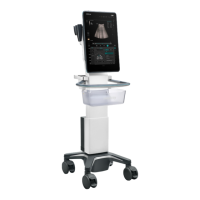
Function description:
The battery management board manages battery charge and discharge. It contains charge and
discharge circuits of eight batteries. In addition, it provides the function of converting 24 VDC to
19 V for output.
The power input includes battery input, 24 VDC input, and 18 V wireless input.
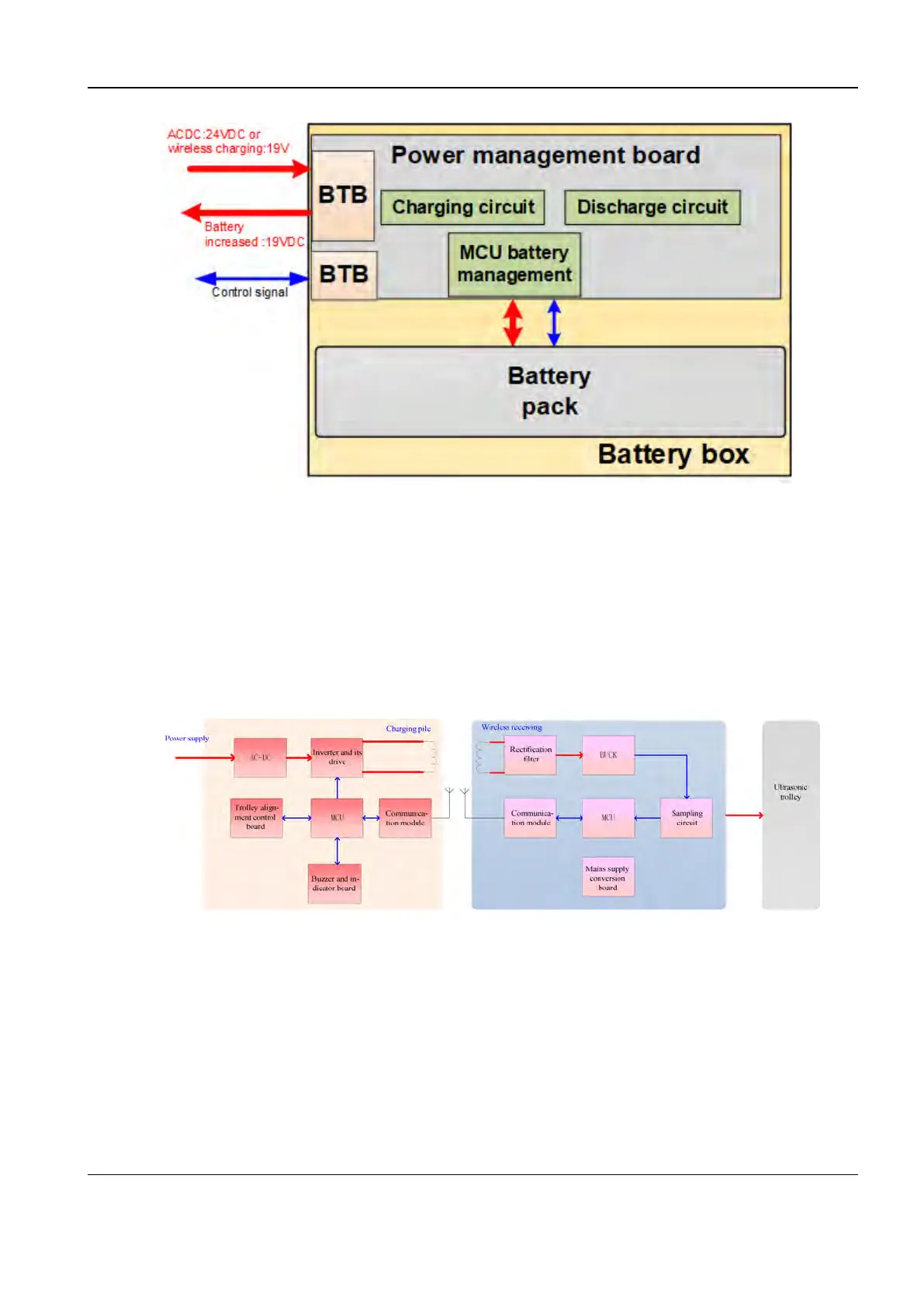
22..33..88..66 Wireless charging module
Block diagram of the wireless charging module
The wireless charging system of ultrasound trolley is divided into charging pile and wireless
receiving module. The charging pile is fixed on the wall, while the wireless receiving module is
mounted on the ultrasound trolley.
Power is transferred between the charging pile and the wireless receiving module through
induction coils based on the electromagnetic induction technology. They communicate with each
other and control information by using the 2.4 G wireless module.
To ensure the power transmission efficiency through induction coils, a wireless charging
alignment scheme of the ultrasound trolley is designed for the system to guide and instruct the
operator of the ultrasound trolley to control the alignment.
Diagnostic Ultrasound System
Service Manual
2 Product Knowledge