Structure and Assembly/Disassembly 9-17
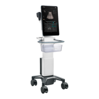
2. Wear the anti-electrostatic glove. Place the control panel assembly on the tool. Unscrew 2 M3
X8 cross panhead screws (red circle) on the keyboard connection plate with cross screwdriver
(M3, M4), and then remove 2 connection plates of the keyboard cover.
If there is no tool available, place the book besides the control panel assembly.
Align the keyboard connection plate with the positioning holes when installing
anticlockwise (yellow circle.
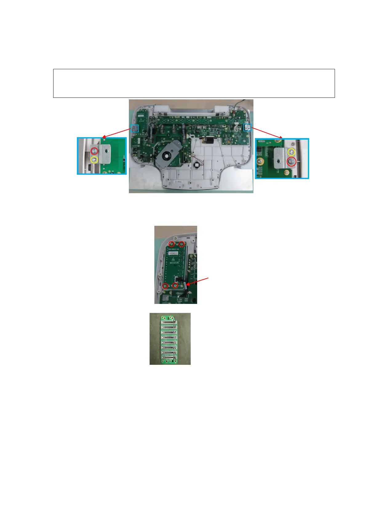
3. Wear the anti-electrostatic glove. Unplug one TGC signal control wire (009-004567-00) from
the TGC board and the control panel. Unscrew 4 PT3X10 cross panhead tapping screws from
TGC board with screwdriver (M3, M4) to remove the TGC board (with the silicon).
board
 Loading...