EasyManua.ls Logo

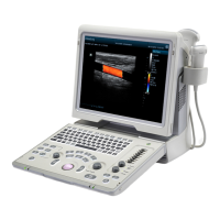
Mindray Z5 Service Manual

Mindray Z5
179 pages
To Next Page IconTo Next Page
Page #1 background imageLoading...
Page #1 background image
Z6/Z6T/Z6S/Z6W/Z6Vet
Z5/Z5BW/Z5T/Z5Vet
Diagnostic Ultrasound System
Service Manual
Revision 15.0

Table of Contents

Other manuals for Mindray Z5

Questions and Answers:

Mindray Z5 Specifications

General IconGeneral
BrandMindray
ModelZ5
CategoryMedical Equipment
LanguageEnglish

Summary

1 Preface

1.1 Meaning of Signal Words

Explains safety signal words like DANGER, WARNING, CAUTION, and NOTE.

1.2 Meaning of Symbols

Defines safety symbols and warning labels used on the ultrasound machine.

1.3 Safety Precautions

Details critical safety measures for operating the ultrasound system safely.

2 Product Specifications

2.1 Overview

Provides an overview of the diagnostic ultrasound system and its intended use.

2.2 Specifications

Lists detailed technical specifications like dimensions, electrical, environmental, and monitor specs.

3 System Installation

3.1 Preparations for Installation

Covers prerequisites for system installation, including electrical requirements and conditions.

3.2 Unpacking

Details the procedure for safely unpacking the ultrasound system components.

3.3 Installation of Main Unit

Guides on installing the main components of the ultrasound system.

3.4 Installing Peripherals

Instructions for connecting and installing supported peripherals like printers and scanners.

3.5 System Configuration

Steps for configuring system settings, presets, and network options for optimal use.

4 Hardware Principle

4.1 General Structure of Hardware System

Outlines the overall hardware architecture and component interactions of the system.

4.2 Main Unit

Describes the internal structure and key boards of the main ultrasound unit.

4.3 Power System

Explains the power supply configuration and operational principles of the system.

5 Function and Performance Checking Method

5.1 Instruction

Provides guidance on verifying the main functions and performance of the ultrasound product.

5.2 Checking System Status

Details procedures for checking the system's running status and ambient conditions.

5.3 General exam

Outlines the general examination process for checking system components like the control panel and display.

5.4 Function Checks

Describes how to perform checks on various imaging modes (B, Color, Doppler, M) and peripherals.

5.5 Performance Test

Details the process and content for testing system performance, including resolution and depth.

6 Software Upgrade and Maintenance

6.1 Enter the Maintenance Window

Steps to access the system's maintenance mode for software operations.

6.2 System Software Installation/ Restoration

Procedures for restoring or installing the operating system and Doppler software.

6.3 Installation of Optional Devices

Guide on installing additional software options and modules for the system.

6.4 Data Backup and Storage

Instructions for backing up and restoring system settings and patient data.

6.5 Software Maintenance

Covers procedures for product configuration and log maintenance.

6.6 Display Parameter Setting

Details how to adjust display parameters and perform monitor maintenance.

7 Structure and Assembly/Disassembly

7.1 Structure of the Complete System

Provides an exploded view of the complete ultrasound system and its main assemblies.

7.2 Field Replaceable Unit

Lists components that can be replaced in the field, including part numbers and compatibility.

7.3 Preparations

Outlines necessary tools, engineers, and preparations before disassembling equipment.

7.4 Assembly/Disassembly

Detailed steps for disassembling and assembling main modules and boards of the system.

8 System Diagnosis and Support

8.1 General Status Indicator

Explains the status indicators on the control panel and their meanings.

8.2 Starting Process of the Whole System

Describes the step-by-step process of the system powering on from BIOS to OS.

8.3 Alarming and Abnormal Information

Lists common alarms, abnormal conditions, and their corresponding log records and suggestions.

9 Care and Maintenance

9.1 Overview

Introduces recommended procedures for system care and maintenance.

9.2 Cleaning

Provides detailed instructions for cleaning the system components and peripherals.

9.3 Checking

Outlines general checks, system function checks, and peripheral/option checks.

10 Troubleshooting of Regular Malfunctions

10.1 System cannot be powered on

Guides on diagnosing and resolving issues where the system fails to power on.

10.2 System Cannot Start up Normally

Addresses problems related to the system starting up but not functioning correctly.

10.3 Image Fault

Covers common issues related to image quality and display faults.

10.4 Probe Socket System Malfunction

Troubleshooting steps for issues related to probe recognition and socket functionality.

10.5 IO Interface System

Diagnoses problems related to the IO interface, including video, USB, and network connectivity.

10.6 Control Panel

Troubleshoots issues with the control panel, keys, trackball, and encoders.

10.7 LCD Display

Provides solutions for problems related to the LCD display, such as blank screens or no signal.

Appendix A ELECTRICAL SAFETY INSPECTION

1- Power Cord Plug

Inspects the power cord plug for physical damage, pin condition, and strain relief.

2- Device Enclosure And Accessories

Conducts visual and contextual inspections of the device enclosure and accessories for damage or issues.

3- Device Labeling

Verifies the presence and legibility of all required manufacturer and safety labels on the device.

4- Protective Earth Resistance

Measures the protective earth resistance to ensure electrical safety compliance.

5- Earth Leakage Test

Performs earth leakage tests to measure current leakage under various conditions.

6- Patient Leakage Current

Measures patient leakage current between applied parts and mains earth for safety.

7- Mains on Applied Part Leakage

Tests mains voltage applied to parts to ensure safety and compliance.

Appendix B Phantom Usage Illustration

Targets Disposal of Phantom KS107BD

Describes the layout and types of targets within the KS107BD phantom for testing.

Line Target System

Explains the different groups of nylon line targets used for performance testing.

Related product manuals