Structure and Assembly/Disassembly 7-25
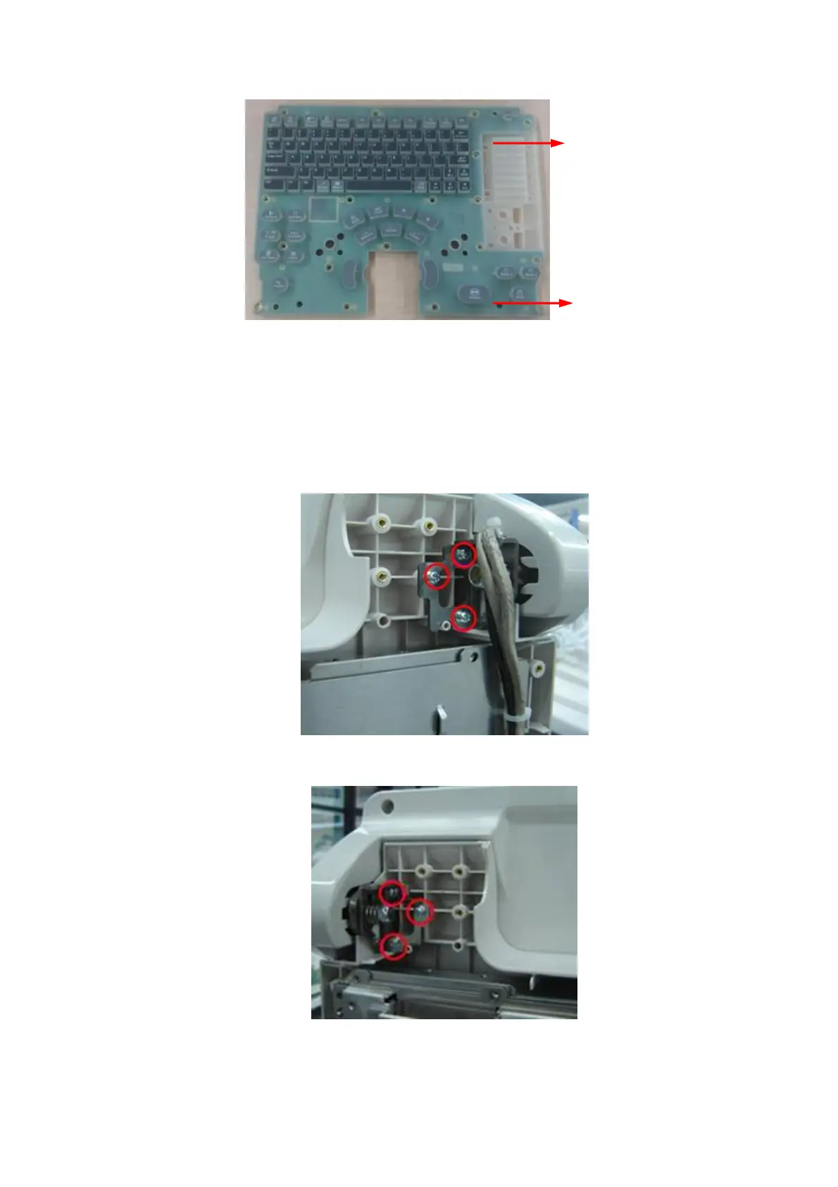
Figure 7-37 Disassemble the Control Panel (3)
7.4.7 Display Assembly
1. Remove rear cover assembly of the main unit (referring to 7.4.1 the 1~4 step)
2. Remove combination screws (6 M3X8) used to be secured the monitor on the front cover of
the main unit by a screwdriver.
Figure 7-38 Screws on the Right of the Display Assembly
Figure 7-39 Screws on the Left of the Display Assembly
3. Cut off cable ties connecting the main unit on the display by diagonal cutting pliers, and then