EasyManua.ls Logo

Mindray M9 User Manual

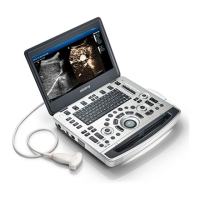
Mindray M9
267 pages
To Next Page IconTo Next Page
Page #1 background imageLoading...
Page #1 background image
M9/M9T/M9CV/M9GI/M9Vet/
M8/M8CV/M8T/M8GI/M8 Elite
Diagnostic Ultrasound System
Service Manual (Advanced)
Revision 25.0

Table of Contents

Questions and Answers:

Mindray M9 Specifications

General IconGeneral
TypePortable Ultrasound System
BatteryRechargeable lithium-ion battery
Battery LifeUp to 90 minutes
Display15.6 inch high resolution LED monitor
Imaging ModesB, M, Color, Power, PW, CW
TransducersLinear, Convex, Phased Array
Transducer Ports3
Probe Connectors3
ConnectivityDICOM, USB, HDMI
Operating SystemWindows-based

Summary

Safety Precautions

Meaning of Signal Words

Defines signal words like DANGER, WARNING, CAUTION, and NOTE used in the manual for safety instructions.

Symbols

Explains safety symbols and warning labels used on the ultrasound machine and its components.

Safety Precautions

Details essential safety precautions for operating the ultrasound system and using probes.

Product Specifications

Introduction

Provides an overview of the diagnostic ultrasound system's intended use and general appearance.

System Appearance

Illustrates the physical components and layout of the ultrasound system, labeling key parts.

Trolley Appearance

Shows the physical components and layout of the mobile trolley, labeling key parts.

Peripherals Supported

Lists the compatible peripheral devices that can be connected to the ultrasound system.

Specifications

Outlines the technical specifications including dimensions, electrical, environmental, and monitor details.

System Installation

Installation Preparations

Covers essential preparations for system installation, including electrical and environmental requirements.

Installation Condition

Specifies the required space, ventilation, and network environment for proper system installation.

Unpacking

Provides instructions and duration for unpacking the system components, including trolley and main unit.

Installation of Whole Device

Details the process of connecting power, ECG leads, and ultrasound probes to the system.

Installing Peripherals

Guides on connecting essential peripherals like footswitch, USB devices, printers, and barcode readers.

System Configuration

Covers system configuration steps including presets, network settings, DICOM, and security.

Product Principle

General Structure of Main Unit’s Hardware System

Provides a schematic overview of the main unit's hardware architecture and its components.

Main Board

Details the main board's components including power supply, backend, and frontend sections.

Control Panel

Describes the structure and functions of the control panel unit, including its boards and diagrams.

Trolley Power Supply

Details the trolley power supply system, including its components and connections.

System Power-on Control

Illustrates the system power-on process and the controlling signals involved.

Checking Performance and Functions

Checking System Status

Details how to check the system's running status and working conditions, including environmental factors.

General Check

Outlines the procedures and criteria for performing general checks on the control panel, monitor, peripherals, and I/O interface.

Functions Checking

Describes the process for checking system functions like imaging modes, measurements, and probe usage.

Performance Test

Details test procedures and content for evaluating system performance, including resolution and depth.

Software Installation & Maintenance

Enter Maintenance

Explains how to log in and enter the maintenance mode for system settings and operations.

Activating Windows 10 Operating System

Guides on activating the Windows 10 operating system, both online and via phone.

Software Maintenance

Covers software maintenance tasks such as log export and data backup/storage.

Data Backup and Storage

Details procedures for managing preset data and performing patient data backup and restoration.

Field Replaceable Unit

Explosive View

Displays an exploded view of the system's main assemblies, labeled with identification codes.

Assembly Explosive View

Provides detailed exploded views of assemblies like the monitor, control panel, main unit, and trolley.

Structure and Assembly/Disassembly

Structure of the Complete System

Illustrates the exploded view of the main unit and the structure of the mobile trolley.

Main Unit Assembly/Disassembly

Details the procedures for disassembling and assembling the main unit's parts and hardware boards.

Trolley Assembly/Disassembly

Provides step-by-step instructions for assembling and disassembling the mobile trolley and its components.

Installation of Option Modules

Installation of Optional Devices to Software

Guides on installing, promoting, and uninstalling optional software devices and their key files.

Installation of the Accessory Kits and Optional Devices to Hardware

Details the installation of accessory kits and optional hardware devices, referencing specific chapters.

System Diagnosis and Support

General Status Indicator

Explains the meaning and status definitions of various indicators on the control panel and the whole machine.

Get Whole Machine Started

Outlines the step-by-step process of starting the ultrasound machine, from power-on to Doppler interface.

Alarming and Abnormal Information

Lists common alarming tips, their corresponding LOG records, and suggested solutions for errors.

Self-test

Details the introduction, procedures, and reports for self-testing the system's hardware and software.

Care and Maintenance

Overview

Provides an overview of maintenance procedures and lists necessary tools, devices, and consumables.

Cleaning

Details the process for cleaning the system components and peripherals, including specific tools and methods.

Check

Outlines procedures for general checks, system function checks, and checks for peripherals and optional functions.

Mechanical Safety Inspection

Describes the process for inspecting the mechanical strength and function of the ultrasound system's components.

Troubleshooting of Regular Malfunctions

Troubleshooting as the System is Disabled to Power On

Provides guidance on troubleshooting issues related to the system failing to power on, including related modules and key points.

The System Cannot Perform Troubleshooting

Offers solutions for scenarios where the system cannot perform its intended functions, covering modules and key troubleshooting points.

Image Troubleshooting

Addresses common image-related problems, their causes, and solutions, focusing on modules and key points.

Troubleshooting Control Panel

Provides troubleshooting steps for issues with the control panel, including related modules and key points.

Troubleshooting LCD Display

Details troubleshooting for LCD display issues, covering related modules, key points, and specific monitor problems.

Troubleshooting for ECG Module

Offers guidance for troubleshooting the ECG module, including related modules, key points, and specific fault descriptions.

Appendix A Electrical Safety Inspection

ELECTRICAL SAFETY INSPECTION

Outlines procedures for electrical safety inspection, covering power cord plug, device enclosure, and labeling.

ELECTRICAL SAFETY INSPECTION

Continues electrical safety inspection procedures, focusing on device labeling and protective earth resistance.

ELECTRICAL SAFETY INSPECTION

Details Earth Leakage and Patient Leakage Current tests as part of electrical safety inspection.

ELECTRICAL SAFETY INSPECTION

Covers Mains on Applied Part Leakage and Patient Auxiliary Current tests for electrical safety.

Appendix B Phantom Usage Illustration

Appendix C Description of Self-test Test Items

Z0101 Hard Disk Verify Test

Describes the self-test procedure for verifying hard disk integrity and analyzing potential failures.

Z0201 PC Module and DSP FPGA Interconnection Test

Details the self-test for PC module and DSP FPGA interconnection, including analysis and suggestions for failure.

Z0202 DSP FPGA DDRIII Test

Explains the DSP FPGA DDRIII self-test, covering test content, analysis, and suggestions for failure.

Z0203 DSP FPGA and TRA Interconnection Test (Control Interface)

Describes the self-test for DSP FPGA and TRA interconnection, focusing on control interface communication.

Z0204 TRA AFE SPI Interface Test

Details the TRA AFE SPI interface self-test, including content, analysis, and suggestions for failure.

Z0205 TRA AFE Digital Interface Test

Explains the TRA AFE digital interface self-test, covering analysis and suggestions for failure.

Z0206 ATGC Function Test

Describes the ATGC function self-test, including content, analysis, and suggestions for failure.

Z0207 TRA Transmission and Reception Function Test

Details the TRA transmission and reception function self-test, covering analysis and suggestions for failure.

Z0208 DSP FPGA and EC ARM Interconnection Test

Explains the DSP FPGA and EC ARM interconnection self-test, including analysis and suggestions for failure.

Z0209 DSP FPGA and SM ARM Interconnection Test

Describes the DSP FPGA and SM ARM interconnection self-test, including analysis and suggestions for failure.

Z0210 System Voltage Test

Details the system voltage self-test, covering analysis and suggestions for failure.

Z0211 System Temperature Test

Explains the system temperature self-test, including analysis and suggestions for failure.

Z0212 Fan Speed Test

Describes the fan speed self-test, covering analysis and suggestions for failure.

Z0213 Speaker Test

Details the speaker self-test, including analysis and suggestions for failure.

Z0214 WIFI Function Test

Explains the WIFI function self-test, covering analysis and suggestions for failure.

Z0125 4D Overcurrent Protecting Status Test

Describes the 4D overcurrent protecting status self-test, including analysis and suggestions for failure.

Z0216 4D Drive Circuit Test

Details the 4D drive circuit self-test, covering analysis and suggestions for failure.

Z0217 TEE Temperature Signal Test

Explains the TEE temperature signal self-test, including analysis and suggestions for failure.

Z0218 TEE Angle Signal Test

Describes the TEE angle signal self-test, covering analysis and suggestions for failure.

Z0301 DSP FPGA and TRB Interconnection Test (Control Interface)

Details the DSP FPGA and TRB interconnection self-test for control interface.

Z0302 TRB AFE SPI Interface Test

Explains the TRB AFE SPI interface self-test, including analysis and suggestions for failure.

Z0303 TRB AFE Digital Interface Test

Describes the TRB AFE digital interface self-test, covering analysis and suggestions for failure.

Z0304 DSP FPGA and TRA&TRB Interconnection Test (Data Interface)

Details the DSP FPGA and TRA&TRB interconnection self-test for data interface.

Z0305 TRB Transmission and Reception Function Test

Explains the TRB transmission and reception function self-test, covering analysis and suggestions for failure.

Z0401 DSP FPGA and PHV ARM Interconnection Test

Describes the DSP FPGA and PHV ARM interconnection self-test, including analysis and suggestions for failure.

Z0402 CW Mode Test

Details the CW mode self-test, covering analysis and suggestions for failure.

Z0403 PHV Mode Test

Explains the PHV mode self-test, including analysis and suggestions for failure.

Z0404 HV Test

Describes the HV self-test, covering analysis and suggestions for failure.

Z0501 Light Sensor Auto Adjust Function Test

Details the light sensor auto adjust self-test, including analysis and suggestions for failure.

Z0601 Keyboard USB Interconnection Test

Explains the keyboard USB interconnection self-test, covering analysis and suggestions for failure.

Z0602 Keyboard Key, Encoder, TGC, Trackball Test

Describes the keyboard, encoder, TGC, trackball self-test, including test description and suggestions.

Z0603 Keyboard Key and Trackball LED Test

Details the keyboard key and trackball LED self-test, covering test content and suggestions.

Z0701 LCD Monitor I2C Interconnection Test

Explains the LCD monitor I2C interconnection self-test, including analysis and suggestions for failure.

Z0702 LCD Monitor Adjust Data Check Test

Describes the LCD monitor adjust data check self-test, covering analysis and suggestions for failure.

Z0703 LCD Monitor Brightness Control Test

Details the LCD monitor brightness control self-test, including analysis and suggestions for failure.

Z0704 LCD Monitor Backlight Control Test

Explains the LCD monitor backlight control self-test, covering analysis and suggestions for failure.

Z0801 Left Battery I2C Interconnection Test

Describes the left battery I2C interconnection self-test, including analysis and suggestions for failure.

Z0802 Right Battery I2C Interconnection Test

Details the right battery I2C interconnection self-test, covering analysis and suggestions for failure.

Z0803 Left Battery Test

Explains the left battery self-test, including analysis and suggestions for failure.

Z0804 Right Battery Test

Describes the right battery self-test, covering analysis and suggestions for failure.

Z0901 ECG Module Information Read Test

Details the ECG module information read self-test, including analysis and suggestions for failure.

Z0902 ECG Module Self Test

Explains the ECG module self-test, covering analysis and suggestions for failure.

Related product manuals