EasyManua.ls Logo

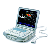
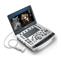
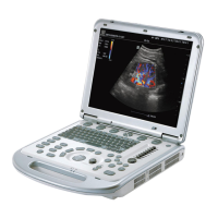
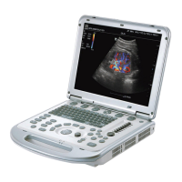
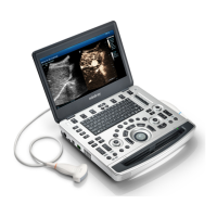
Mindray M8

Mindray M8
267 pages
To Next Page IconTo Next Page
Loading...
M9/M9T/M9CV/M9GI/M9Vet/
M8/M8CV/M8T/M8GI/M8 Elite
Diagnostic Ultrasound System
Service Manual (Advanced)
Revision 25.0

Table of Contents

Questions and Answers:

Mindray M8 Specifications

General IconGeneral
PortabilityPortable
Display Size15 inches
Display TypeLED
ConnectivityUSB, Ethernet
Monitoring ParametersColor Doppler, Pulsed Wave Doppler, Continuous Wave Doppler, M mode
Operating ModesColor Doppler, Pulsed Wave Doppler, Continuous Wave Doppler
ApplicationsGynecology, Cardiology, Urology, Vascular, Musculoskeletal
Operating SystemWindows-based
Imaging ModesColor Doppler, Power Doppler, Pulsed Wave Doppler, Continuous Wave Doppler, M-Mode

Summary

Safety Precautions

Meaning of Signal Words

Explains the meaning of DANGER, WARNING, CAUTION, and NOTE signal words used in the manual.

Symbols

Provides location and information of safety symbols and warning labels used in the manual.

Safety Precautions

Lists crucial safety measures for patient and operator safety during system use.

Product Specifications

Introduction

Outlines the intended use and general appearance of the diagnostic ultrasound system.

Specifications

Details the electrical, environmental, and monitor specifications of the system.

System Installation

Installation Preparations

Covers electrical requirements, grounding, and EMI limitations for system installation.

Unpacking

Provides instructions for unpacking the system, including tools and duration.

Installation of Whole Device

Guides on connecting power, ECG, and ultrasound probes to the main unit.

Installing Peripherals

Details the connection procedures for various peripherals like footswitch, printers, and readers.

Wired Network Connection

Explains how to connect the system to a network using a USB to LAN adapter.

System Configuration

Covers system setup, presets, network configuration, DICOM/HL7, and security settings.

Product Principle

General Structure of Main Units Hardware System

Describes the overall hardware structure of the main unit, including key components.

Main Board

Details the components and functions of the main board, including power supply, backend, and frontend.

Checking Performance and Functions

Description

Introduces the chapter on checking main functions and performance methods.

Checking System Status

Outlines methods for checking the system's running status and working condition.

General Check

Provides procedures and criteria for checking the control panel, monitor, peripherals, and ECG module.

Functions Checking

Details how to check various system functions like imaging modes, measurement, and cine review.

Performance Test

Describes test procedures for resolution, detection depth, geometric positioning, and blind area.

Software Installation & Maintenance

Enter Maintenance

Guides on logging into the system as a service user for maintenance operations.

Software InstallationRestoration

Refers to the Software Recovery Guide for system operations and Doppler restoration.

Activating Windows 10 Operating System

Explains procedures for online and phone activation of Windows 10 OS.

Enter Windows

Provides instructions on accessing the Windows system using a password.

Software Maintenance

Covers software maintenance tasks like log export.

Data Backup and Storage

Details procedures for preset data management, patient data backup, and restoration.

Introduction on HDD Partition Data

Provides information on HDD partition data structure and distribution.

Field Replaceable Unit

Explosive View

Presents an exploded view of the system's main assemblies.

Assembly Explosive View

Shows detailed exploded views of monitor, control panel, main unit, cables, accessories, and trolley.

Structure and AssemblyDisassembly

Structure of the Complete System

Illustrates the structure of the main unit and mobile trolley assemblies.

Main Unit AssemblyDisassembly

Provides detailed steps for disassembling and assembling the main unit's parts and hardware boards.

Trolley AssemblyDisassembly

Outlines the procedures for assembling and disassembling the mobile trolley, including tools and engineers required.

Installation of Option Modules

Installation of Optional Devices to Software

Guides on installing optional software devices, including key file installation and trial activation.

Installation of the Accessory Kits and Optional Devices to Hardware

Details the installation of accessory kits and optional hardware devices for the system.

System Diagnosis and Support

General Status Indicator

Explains the meaning of power-on, battery, AC, standby, and hard disk status indicators.

Get Whole Machine Started

Describes the step-by-step process of starting the ultrasound system, including BIOS and OS loading.

Alarming and Abnormal Information

Lists common alarming tips, LOG records, and suggestions for power, temperature, and fan errors.

Self-test

Covers self-test introduction, maintenance self-test procedures, user self-test, and test reports.

Care and Maintenance

Overview

Introduces the maintenance procedures and lists necessary tools, devices, and consumables.

Cleaning

Provides detailed instructions for cleaning the system, monitor, trackball, peripherals, and probes.

Check

Outlines general checks, system function checks, peripheral checks, and mechanical safety inspections.

Troubleshooting of Regular Malfunctions

Troubleshooting as the System is Disabled to Power On

Addresses issues related to the system failing to power on, including related modules and causes.

The System Cannot Perform Troubleshooting

Discusses problems where the system cannot perform troubleshooting, identifying potential faulty modules.

Image Troubleshooting

Provides solutions for image-related issues like no echo, dark strips, and noise.

Troubleshooting Control Panel

Covers common faults with the control panel, including buzzer alarms, key failures, and trackball issues.

Troubleshooting LCD Display

Addresses issues with the LCD display, such as no display or incorrect display via HDMI.

Troubleshooting for ECG Module

Offers solutions for ECG module problems, including failure to open functions or incorrect waveform display.

Appendix A Electrical Safety Inspection

Power Cord Plug

Details visual and contextual checks for the power cord plug and strain relief.

Device Enclosure And Accessories

Outlines visual and contextual inspections for the device enclosure and accessories.

Device Labeling

Specifies checking for the presence and legibility of manufacturer and warning labels.

Protective Earth Resistance

Describes the procedure and limits for testing protective earth resistance using a safety analyzer.

Earth Leakage Test

Explains how to perform Earth Leakage tests and outlines failure conditions and limits.

Patient Leakage Current

Details the procedure for measuring patient leakage current and failure conditions.

Mains on Applied Part Leakage

Describes the Mains on Applied Part leakage test procedure, including voltage and polarity conditions.

Patient Auxiliary Current

Covers the procedure for measuring patient auxiliary current and failure analysis.

Appendix B Phantom Usage Illustration

Appendix C Description of Self-test Test Items

Z0101 Hard Disk Verify Test

Explains testing hard disk files against archived data and failure analysis.

Z0201 PC Module and DSP FPGA Interconnection Test

Details testing PCIe communication between PC and DSP FPGA modules.

Z0202 DSP FPGA DDRIII Test

Covers read/write tests for DSP FPGA DDRs and analysis of failures.

Related product manuals