Product Principle 4-11
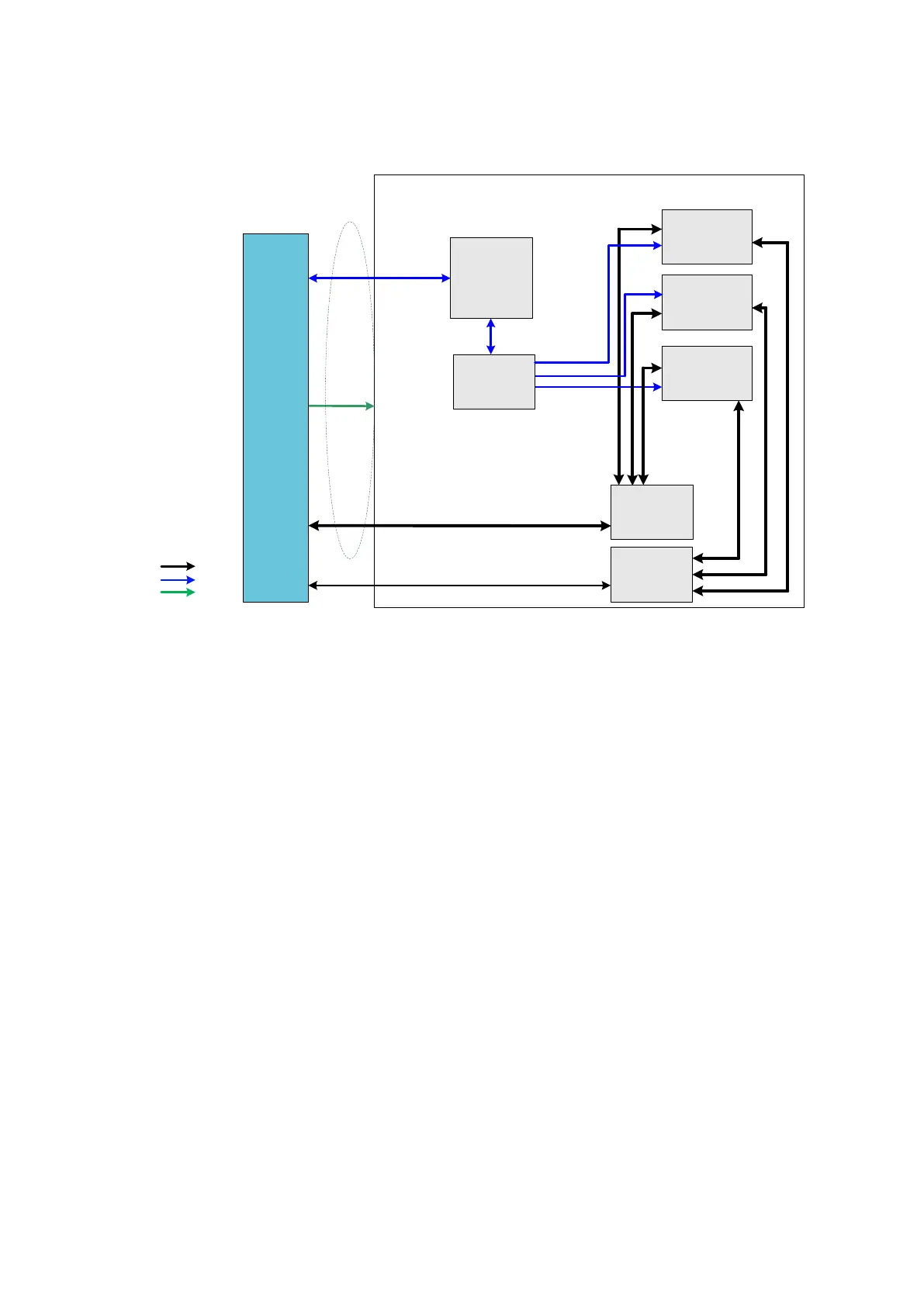
4.9 Probe Extension Board
Probe Extend Board
C probe socket
260pin
B probe socket
260pin
A probe socket
260pin
POUT signal switch
(relay set)
CPLD
Probe signal
4D&TEE signal
Probe control
circuit
Probe control signal
12V/5.7V
/+100V/-100V
128 channel
Transmitting/receiving signal
260PIN
probe
connector
Probe Board
Communication
&control
Power supply
Ultrasound signal
4D&TEE signal
switch
(relay set)
Figure 4-9 Hardware diagram of probe extension board
Function description:
Supports 192/128 array probe, 4D probe, phased array probe, bi-plane probe, and other
nominal probes, etc.
Implements the switch of 192 array probe within the probe. Probe board only supports 128
channels.
Probe board contains three 260pin Mini probe sockets.
Supports the retrieving of three probes’ IDs and the switch among three probe socket. ID
recognition and the circuit of probe switch are independent to each other.