miniDSP Ltd, Hong Kong / www.minidsp.com / Features and specifications subject to change without prior notice 23
4.3 PLUGIN CONFIGURATION GUIDE
The miniDSP DDRC-24 is adaptable to many system configurations. This section describes several common
system types and how to configure the DDRC-24 plugin for them. For full details of the referenced signal
processing blocks, see Section 9.
4.3.1 Stereo room correction
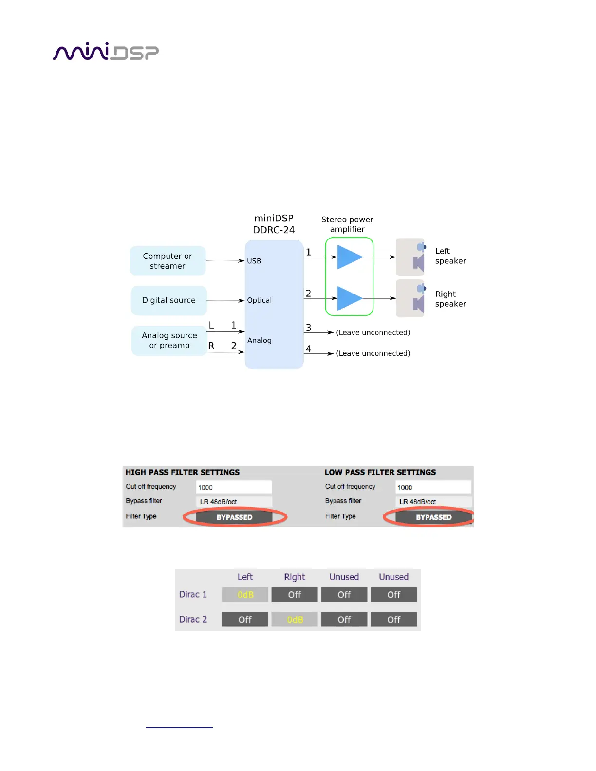
In a stereo room correction configuration, the plugin is set up to route the selected input through to output
channels 1 and 2. This diagram illustrates the connections:
On the Outputs tab:
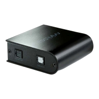
Rename the output channels (from left to right) to “Left”, “Right”, “Unused” and “Unused”.
Mute channels 3 and 4 (labeled “Unused”).
Set the crossover filters of channels 1 and 2 (“Left” and “Right”) to Bypass, as shown here:
On the Routing tab, set the matrix like this:
After you have set up the DDRC-24 plugin, save your configuration to a file. Then quit the DDRC-24 plugin, start
Dirac Live Calibration Tool, and run the Dirac Live calibration as described in sections 5 and 6.