FA-1025T Installation and Operation Manual
9
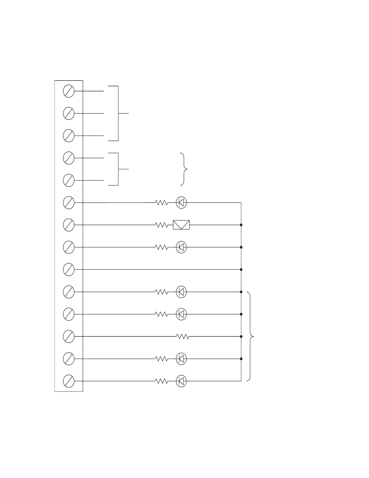
Figure 6: Alarm and trouble relay contacts and remote annunciation
wiring instructions
Auxiliary common
alarm relay contacts
28VDC, 3A (resistive)
Common trouble
relay contacts
28VDC, 3A
(resistive)
Cut JW3 for N.O.
Cut JW4 for N.C.
N.O.
C
N.C.
TB3
TRL
TRB
A.C. ON
50 mA max./zone
24VDC, 50 mA max.
unsupervised
unsupervised
24VDC, 50 mA max.
1.5K
1.5K
1.5K
remote trouble
LED (amber)
buzzer
LED (green)
remote trouble
Cut JW7 to enable lamp
supervision for the remote
annunciator alarm zones.
If LEDs are supervised,
jumper to the unused out-
puts to common (+) with a
series 3.9K resistor.
1.5K
remote A.C. ON
common (+) 24VDC, 250mA max.
Z1 zone 1 remote alarm
remote alarm
LED (red)
LED (red)
1.5K
3.9K
Z3 zone 2
Z3 zone 3
Z4 zone 4
Z5 zone 5
1.5K
1.5K
remote alarm
LED (red)
remote alarm
LED (red)
remote alarm
LED (red)