Appendix B: Battery Calculations (Selection Guide)
14
Appendix B: Battery Calculations (Selection Guide)
Use the form below to determine the required batteries.
Total Current Requirement
ALARM (B)______ Amps.
Battery Capacity Requirement
(
[STANDBY (A) ______ ] X [(24 or 60 Hours) ________ ]) + ([ALARM (B) ______ ] X [
♣
Alarm in Hr.] ________) = (C) ________AH
Battery Selection
Multiply (C) by 1.20 to derate battery.
* Assuming three initiating circuits in alarm.
♣
Use 0.084 for five minutes of alarm or 0.5 for thirty minutes of alarm as a multiplier figure.
♦
Using the MIR-525/U 2-wire smoke detector. See Appendix A, for other available smoke detectors .
IMPORTANT NOTICE
The main AC branch circuit connection for the Fire Alarm Control Unit must provide a dedicated
continuous power without provision of any disconnect devices. Use #12 AWG wire with 600-volt
insulation and proper over-current circuit protection that complies with the local codes.
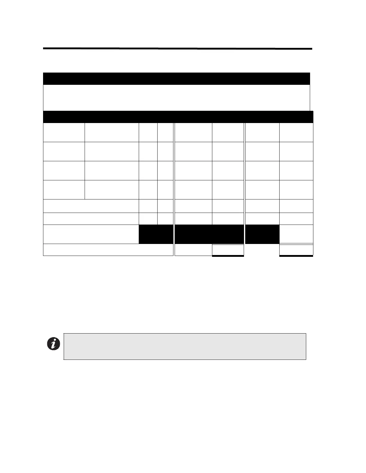
Power Requirements (All currents are in amperes)
Model
Number
Description Qty Standby
Total
Standby
Alarm
Total
Alarm
FA-1025T
Fire Alarm, 5 Det,
2 Sig
X 0.114 = 0.200 =
RA-105
Annunciator, 5
Circuits
X 0.016 = 0.032 =
RTI-1
Remote Trouble
Indicator
X 0.035 = 0.035 =
2-Wire Smoke Detectors X
♦
0.0001
= * 0.090 = 0.090
4-Wire Smoke Detectors X = =
Signal Load (bells, horns,
strobes, and etc.)
=
Total currents (Add above currents) Standby (A)(B)
Note: Batteries BA-104 (4.0AH) and BA-1065(6.5AH) fit into the backboxes; all larger
batteries such as BA-110(10AH) and the BA-117(17AH) require an external
battery box.