62
Field Wiring
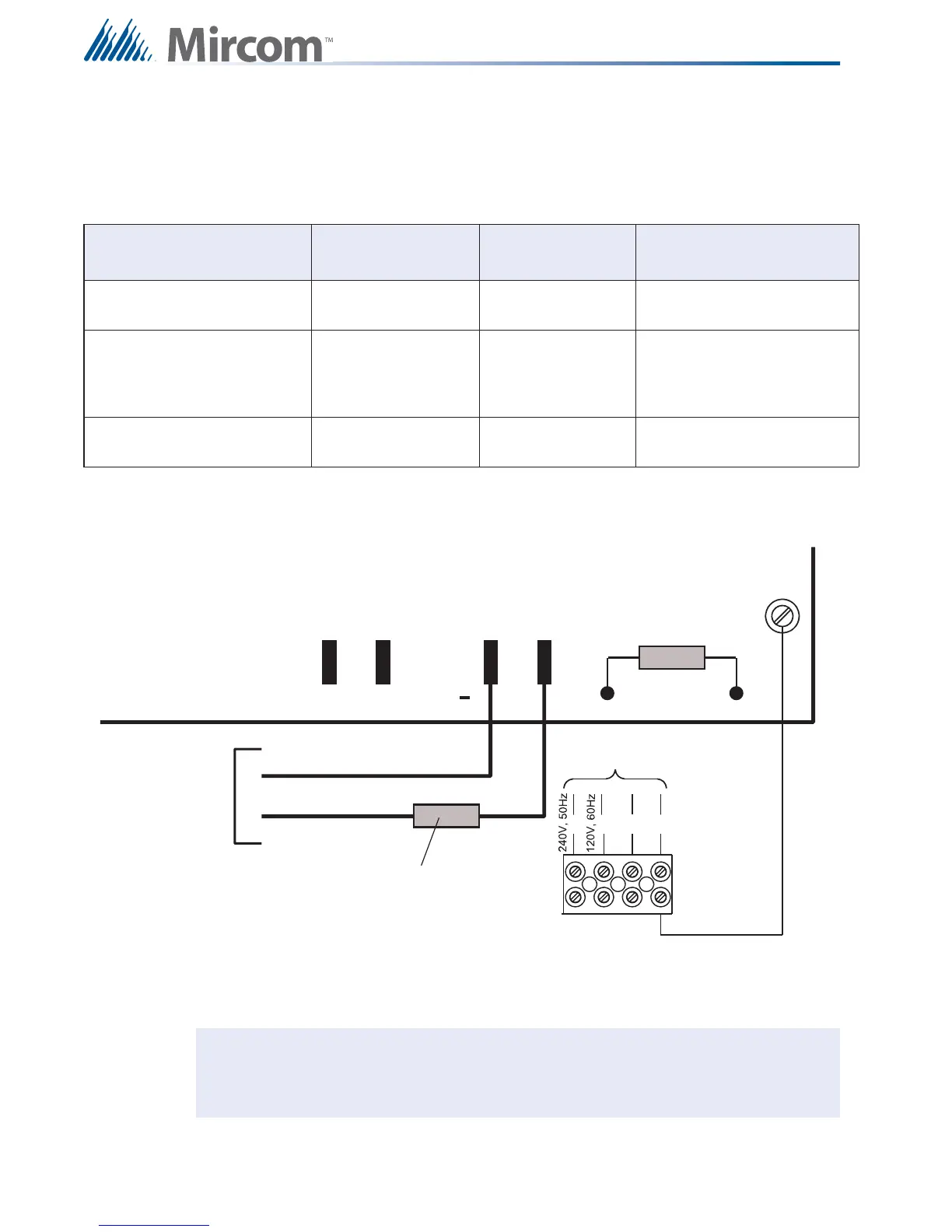
8.7 Power Supply Connections
The power supply is part of the main chassis. The ratings are outlined in Table 13.
Using proper wire gauge, connect as shown in Figure 44. For specifications see 12.0
Appendix A: Specifications.
Figure 44 Power Supply Connections
Table 13 Power Supply Ratings
Model Electrical Input
Ratings
Power Supply
Total Current
Battery Fuse on Main
Module
FX-2003-6DS & FX-2003-
6DS-16LED Main Chassis
120 VAC, 60 Hz, 2A /
240VAC, 50hz, 1A
6 amps maximum
Replace with 20 Amp, 1-1/4"
Fuse
FX-2003-12DS, FX-2003-
12XTDS,FX-2017-12ADS &
FX-2017S-12ADS Main
Chassis
120 VAC, 60 Hz, 2A /
240VAC, 50hz, 1A
12 amps maximum
Replace with 20 Amp, 1-1/4"
Fuse
FX-2009-12DS & FX-2009S-
12DS Main Chassis
120 VAC, 60 Hz, 2A /
240VAC, 50hz, 1A
12 amps maximum
Replace with 20 Amp, 1-1/4"
Fuse
Caution: To prevent sparking, connect batteries after the system’s main A.C. power is
turned ON. Do not exceed power supply ratings.
P13
CONNECT GREEN
EARTH GROUND WIRE
TO MAIN MODULE PCB
MOUNTING SCREW.
N
G
GREEN
TO 24 VDC
BATTERY
BLACK
P11
P10
P12
+
BAT
RED
TO DEDICATED
BRANCH CIRCUIT
L
L
20 Amp
FAST ACTING FUSE
FUSE