DIP Switch Settings
6
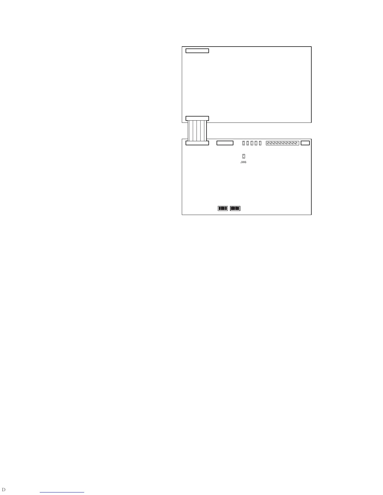
On the RAX-1048(TZ) Adder
Annunciator Chassis:
P1: Connects to the Main Annunciator
Chassis, or to the previous Adder
Annunciator Chassis.
P2: Connects to the Next Adder
Annunciator Chassis.
On the RAM-1032(TZ) Main
Annunciator Chassis:
P2: Connects to the first Adder
Annunciator Chassis.
P3,P11: Not used.
Jumpers: Factory set. Do not change.
Terminals: See Wiring Instructions on
page 3 for details.
SW1, SW2: Set DIP Switches as
described in “DIP Switch Settings” on
page 4.
JW6: RS-485 termination jumper.
Remove on all except for last RAM-
1032(TZ).
On the RAM-1016(TZ) Main Annunciator Chassis:
P2: Not used. No expansion allowed.
P3,P11: Not used.
Jumpers: Factory set. Do not change.
Terminals: See Wiring Instructions on page 3 for details.
SW1, SW2: Set DIP Switches as described in “DIP Switch Settings” on page 4.
JW6: RS-485 termination jumper. Remove on all except for last RAM-1016(TZ).
P2
ADDER ANNUNCIATOR BOARD
P2 P3 JUMPERS TERMINALS P11
SW1 SW2
MAIN ANNUNCIATOR BOARD
P1
JW6

 Loading...


