Page 24
All Units in a TAS-2000 System must operate at the same RS-485 Communication Speed!!
2001 LOBBY UNIT CONFIGURATION
Most of the 2001 Lobby Unit Configuration is set using either the Unit’s own Keypad and Display, or via the PC Configuration Software (see
separate manual). One item that is separately set is the Lobby Unit’s ID and RS-485 Communications Speed. These are set by the SW2 DIP
Switches on the Main Board (see the Main Board diagram in the Lobby Unit Wiring section).
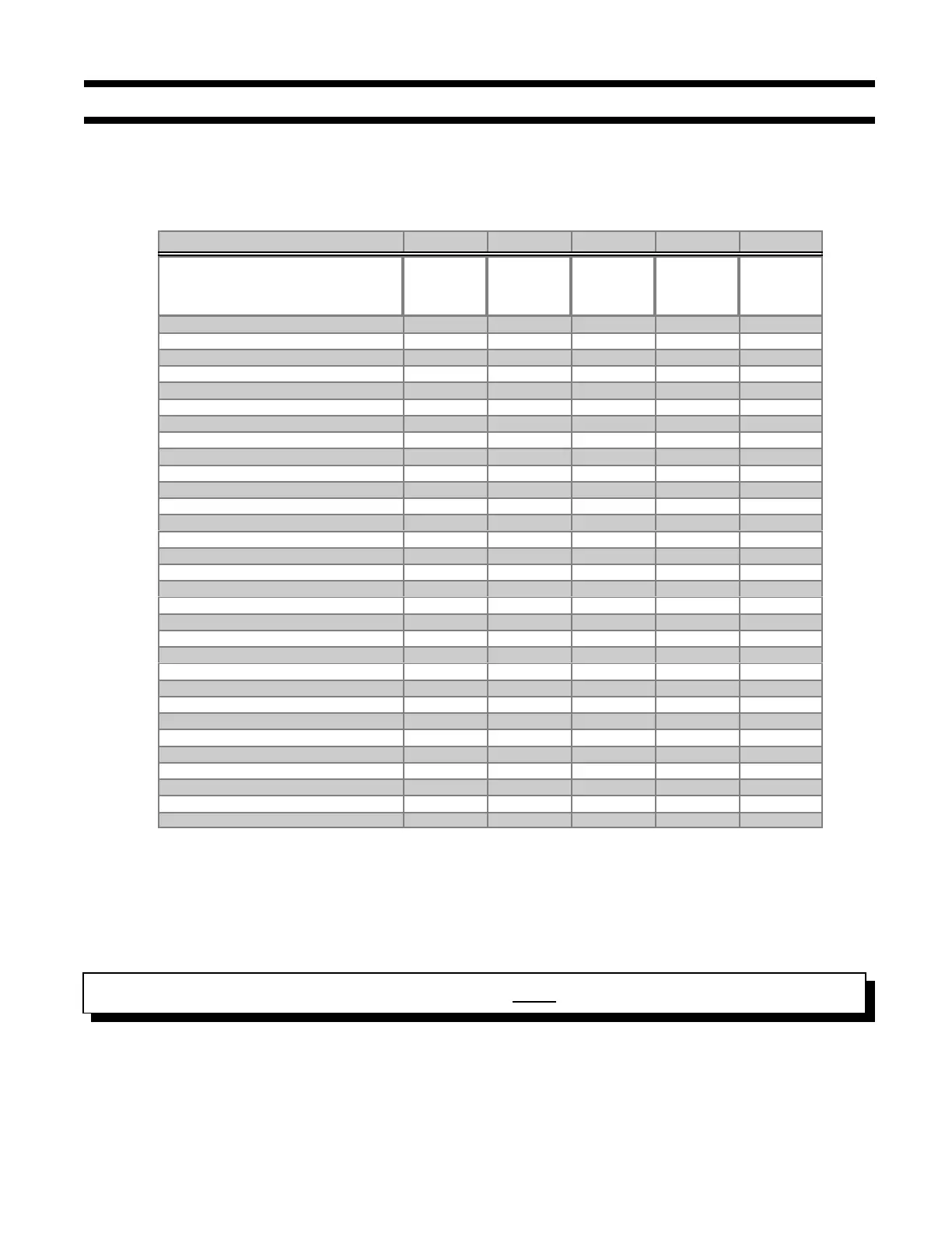
The individual switches are numbered 1 to 8 from the top to the bottom, and are marked as either On-Off or Closed-Open. The first five
switches set the ID ...
2001 Lobby Unit ID # Switch 1 Switch 2 Switch 3 Switch 4 Switch 5
THIS ADDRESS IS NOT
ALLOWED AS LOBBY ID
0 is used for PC ID
ON ON ON ON ON
1 OFF ON ON ON ON
2 ON OFF ON ON ON
3 OFFOFFONONON
4 ON ON OFF ON ON
5 OFF ON OFF ON ON
6ONOFFOFFONON
7 OFF OFF OFF ON ON
8 ONONONOFFON
9 OFF ON ON OFF ON
10 ON OFF ON OFF ON
11 OFF OFF ON OFF ON
12 ON ON OFF OFF ON
13 OFF ON OFF OFF ON
14 ON OFF OFF OFF ON
15 OFF OFF OFF OFF ON
16 ON ON ON ON OFF
17 OFFONONONOFF
18 ON OFF ON ON OFF
19 OFF OFF ON ON OFF
20 ON ON OFF ON OFF
21 OFF ON OFF ON OFF
22 ON OFF OFF ON OFF
23 OFF OFF OFF ON OFF
24 ON ON ON OFF OFF
25 OFF ON ON OFF OFF
26 ON OFF ON OFF OFF
27 OFF OFF ON OFF OFF
28 ON ON OFF OFF OFF
29 OFF ON OFF OFF OFF
30 ON OFF OFF OFF OFF
31 OFF OFF OFF OFF OFF
NOTE: Dip Switch 6 is not used and Switch 7 is ON for an NSL system or OFF for an ADC system.
Every Lobby Unit in a given TAS-2000 System requires a unique ID. These should be assigned starting from “1",
and incrementing by one, i.e. 1, 2, 3, 4 . . . UNIT IDS MUST NOT BE DUPLICATED. The remaining DIP Switch,
Switch 8, defines the Lobby Unit’s RS-485 Communications Speed. This Switch 8 is left in the “OFF” position for
2400 Baud.