MICRO 8
Installation and user manual
Page 11 of 24
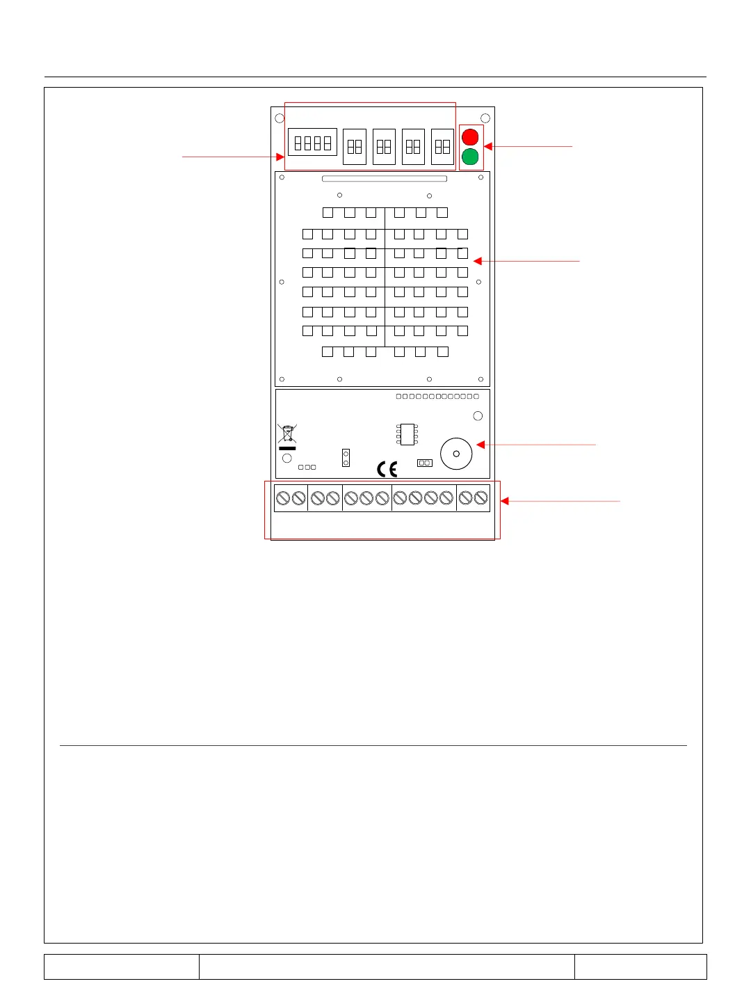
board (RX )
LED
RX ANTENNA
DIP SWITCH
FREQ
0
ON
1 2
0
ON
0
ON
0
ON
1 2
1 2
1 2
SENS
LEVEL
SENS
TIME
ABS
CNF
S/A
LED
ON
TAMPER
IN
TAMPER
OUT
0 A B
RS485
GND VIN
ALARM WARN
TERMINAL BLOCK
-switch description :
frequency setting
signal attenuation level setting
signal attenuation duration setting
detection mode setting (PARAMETER NOT TO CHANGE)
activation of configuration mode
activation of the RS485 module for software management
led activation
board description:
tamper input
tamper output
RS485
alarm output
anti-masking output
: 0 V
+12 Vdc
TERM
BUZZER
MODULE RS485
WITH BUZZER