6. SERVO PROGRAMS FOR POSITIONING CONTROL
6 − 4
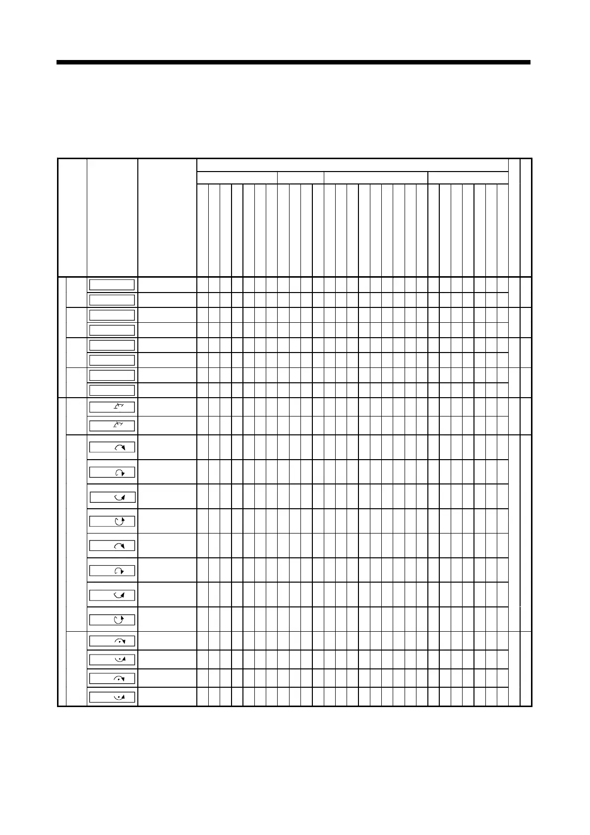
(2) Servo instruction list
The servo instructions that can be used in servo programs, and the positioning
data set for the servo instructions, are indicated in Table 6.2.
For details on the positioning data set for servo instructions, see Section 6.3.
Table 6.2 Servo Instruction List
Positioning Data
Common Settings
Circular
Interpolation
Parameter Block Others
Position-
ing
Control
Instruction
Symbol
Processing Details
Parameter Block No.
Axis
Address/Travel Value
Commanded Speed
Dwell Time
M-Code
Torque Limit Value
Auxiliary Point
Radius
Enter Point
Number of Pitches
Control Unit
Speed Limit Value
Acceleration Time
Deceleration Time
Rapid Stop Deceleration Time
Torque Limit Value
Deceleration Processing on STOP
Input
Allowable Error Range for Circular
Interpolation
S- Curve Ratio
Repeat Condition
Program No.
Commanded Speed (Constant Speed)
Cancel
Start
Skip
FIN Acceleration
Number of Steps
Section for Detailed Explanation
ABS-1
Absolute 1-axis
positioning
∆
!!!
∆∆ ∆∆∆∆∆∆ ∆ ∆∆
1-axis
INC-1
Incremental 1-axis
positioning
∆
!!!
∆∆ ∆∆∆∆∆∆ ∆ ∆∆
4 to
16
7.2
ABS-2
Absolute 2-axes linear
interpolation
∆
!!!
∆∆ ∆∆∆∆∆∆∆ ∆ ∆∆
2-axes
INC-2
Incremental 2-axes linear
interpolation
∆
!!!
∆∆ ∆∆∆∆∆∆∆ ∆ ∆∆
5 to
18
7.3
ABS-3
Absolute 3-axes linear
interpolation
∆
!!!
∆∆ ∆∆∆∆∆∆∆ ∆ ∆∆
3-axes
INC-3
Incremental 3-axes linear
interpolation
∆
!!!
∆∆ ∆∆∆∆∆∆∆ ∆ ∆∆
7 to
20
7.4
ABS-4
Absolute 4-axes linear
interpolation
∆
!!!
∆∆ ∆∆∆∆∆∆∆ ∆ ∆∆
Linear control
4-axes
INC-4
Incremental 4-axes linear
interpolation
∆
!!!
∆∆ ∆∆∆∆∆∆∆ ∆ ∆∆
8 to
23
7.5
ABS
Absolute circular
interpolation by auxiliary
point designation
∆
!!!
∆∆
!
∆∆∆∆∆∆∆ ∆ ∆∆
Auxil-
iary
point
desig-
nation
INC
Incremental circular
interpolation by auxiliary
point designation
∆
!!!
∆∆
!
∆∆∆∆∆∆∆ ∆ ∆∆
7 to
21
7.6
ABS
Absolute circular
interpolation by radius
designation, less than
CW180
°
∆
!!!
∆∆
!
∆∆∆∆∆∆∆∆∆ ∆∆
ABS
Absolute circular
interpolation by radius
designation, CW180
°
or more
∆
!!!
∆∆
!
∆∆∆∆∆∆∆∆∆ ∆∆
ABS
Absolute circular
interpolation by radius
designation, less than
CCW180
°
∆
!!!
∆∆
!
∆∆∆∆∆∆∆∆∆ ∆∆
ABS
Absolute circular
interpolation by radius
designation, CCW180
°
or more
∆
!!!
∆∆
!
∆∆∆∆∆∆∆∆∆ ∆∆
INC
Incremental circular
interpolation by radius
designation, less than
CW180
°
∆
!!!
∆∆
!
∆∆∆∆∆∆∆∆∆ ∆∆
INC
Incremental circular
interpolation by radius
designation, CW180
°
or more
∆
!!!
∆∆
!
∆∆∆∆∆∆∆∆∆ ∆∆
INC
Incremental circular
interpolation by radius
designation, less than
CCW180
°
∆
!!!
∆∆
!
∆∆∆∆∆∆∆∆∆ ∆∆
Radius
desig-
nation
INC
Incremental circular
interpolation by radius
designation, CCW180
°
or more
∆
!!!
∆∆
!
∆∆∆∆∆∆∆∆∆ ∆∆
6 to
20
7.7
ABS
Absolute circular
interpolation by center
point designation, CW
∆
!!!
∆∆
!
∆∆∆∆∆∆∆∆∆ ∆∆
ABS
Absolute circular
interpolation by center
point designation, CCW
∆
!!!
∆∆
!
∆∆∆∆∆∆∆∆∆ ∆∆
INC
Incremental circular
interpolation by center
point designation, CW
∆
!!!
∆∆
!
∆∆∆∆∆∆∆∆∆ ∆∆
Circular interpolation control
Center
point
desig-
nation
INC
Incremental circular
interpolation by center
point designation, CCW
∆
!!!
∆∆
!
∆∆∆∆∆∆∆∆∆ ∆∆
7 to
21
7.8
!
: Must be set
∆
: Set if required
 Loading...