3. POSITIONING SIGNALS
3 − 51
3.4 Special Register (SP.D)
A servo system CPU has 256 special register points from D9000 to D9255.
Of these, the 20 points from D9180 to D9199 are used for positioning control.
The special registers used for positioning are shown in the table below (for the
applications of special registers other than D9180 to D9199, see Appendix 3.2.)
Table 3.3 Special Register List
Refresh Cycle Import Cycle
Signal Name
Number of set axes Number of set axes
A173UHCPU
1 to 20 21 to 32 1 to 20 21 to 32
SV13
A273UHCPU
1 to 12 13 to 24 25 to 32 1 to 12 13 to 24 25 to 32
A173UHCPU
1 to 12 13 to 24 25 to 32 1 to 12 13 to 24 25 to 32
Device
Number
SV22
A273UHCPU
1 to 8 9 to 18 19 to 32 1 to 8 9 to 18 19 to 32
Signal
Direction
D9180
D9181
User usable
D9182
D9183
Test mode request error information At test mode request
D9184 PCPU WDT error cause
At PCPU WDT error
occurrence
D9185
D9186
D9187
Manual pulse generator axis setting error
information
On leading edge of
manual pulse generator
enable
SCPU←PCPU
D9188 User usable
D9189 Error program No.
D9190 Error item information
At start
D9191 At power-on and
D9192
Servo amplifier loading information
10ms 20ms
SCPU←PCPU
D9193
D9194
D9195
User usable
D9196
Personal computer link communication error
code
3.5ms 7.1ms 14.2ms
SCPU←PCPU
D9197
D9198
D9199
User usable
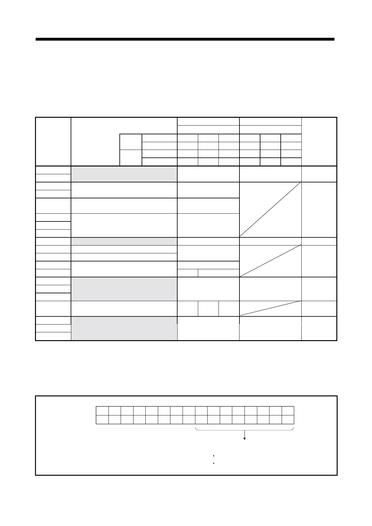
(1) Test mode request error information (D9182, D9183)..............Data from PCPU
to SCPU
If there are starting axis at a test mode request from the peripheral device, a
test mode request error occurs, the error flag (M9078) turns ON, and the
starting/stopping data of the corresponding axis are stored.
Axis16
D9182
D9183
Axis15 Axis14 Axis13 Axis12 Axis11 Axis10 Axis9 Axis8 Axis7 Axis6 Axis5 Axis4 Axis3 Axis2 Axis1
Axis32 Axis31 Axis30 Axis29 Axis28 Axis27 Axis26 Axis25 Axis24 Axis23 Axis22 Axis21 Axis20 Axis19 Axis18 Axis17
b15 b14 b13 b12 b11 b10 b9 b8 b7 b4 b3 b2 b1 b0b6 b5
Stores the operating/stopped
status of each axis
0: Stopped
1: Operating
 Loading...