APPENDICES
APP − 43
3.2 Special Registers (SP.D)
The special registers are data registers used for specific purposes in the
programmable controller. Therefore, do not write data to the special registers in the
program (with the exception of those whose numbers are marked
(Note-2)
in the
table).
Of the special relays, those from D9180 to D9199 are used for positioning control.
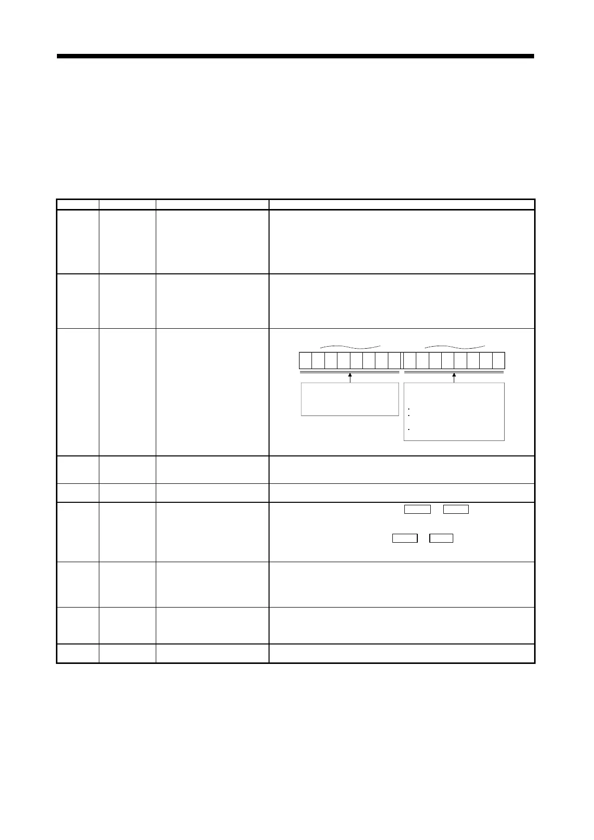
Table 3.2 Special Register List
Number Name Stored Data Explanation
D9000 Fuse blown Number of module with blown fuse
! When modules with a blown fuse are detected, the lowest I/O number of the
detected modules is stored in hexadecimal in this special relay.
(Example: Blown fuses at the output modules Y50 to 6F... "50" is stored in
hexadecimal.)
For monitoring at a peripheral device, use hexadecimal display monitor
operations.
(Cleared when the contents of D9100 are all "0".)
D9002
I/O unit verify
error
I/O module verification error
module number
!
If I/O modules that do not match the registered data are detected when the power
is turned on, the first I/O number of the lowest module number among the
detected modules is stored in hexadecimal (the storage method is the same as for
D9000). When monitoring with a peripheral device, use a hexadecimal display
monitoring operation.
(Cleared when all contents of D9116 to D9123 are reset to zero.)
D9004
(Note-1)
MINI link error
Parameter-set (1 to 8 modules)
states are stored.
! Stores the MINI(S3) link error detection states of the loaded master modules.
b15 b8 b7 b0
8th 7th 6th 5th 4th 3rd 2nd 1st 8th 7th 6th
5th 4th 3rd 2nd 1st
The bit corresponding to the master
module which cannot make data
communication with the PLC CPU
turns ON.
The corresponding bit turns ON
when any of the following signals of
the master module turns ON.
Hardware fault (X0/X20)
MINI(S3) link error detection
(X6/X26)
MINI(S3) link communication error
(X7/X27)
D9005
(Note-4)
AC DOWN
counter
AC DOWN occurrence count
! 1 is added to the stored value each time the input voltage becomes 80% or less of
the rating while the CPU module is performing an operation, and the value is
stored in BIN code.
D9008
(Note-4)
Self-diagnostic
error
Self-diagnostic error number
! 1 is added to the stored value when an error is found as a result of self-diagnosis,
the error number, and the value is stored in BIN code.
D9009
Annunciator
detection
F number at which external failure
has occurred
!
When one of F0 to 2047 is turned on by OUT F or SET F , the F number
detected earliest among the F numbers which have been turned on is stored in
BIN code.
!
D9009 can be cleared by executing a RST F or LEDR instruction. If another F
number has been detected, the clearing of D9009 causes the next number to be
stored in D9009.
D9010 Error step
Step number at which operation
error has occurred
! If access to the module which has been set as a special module could not be
made at a STOP→RUN time, the module No. of the special module is stored.
! When an operation error occurs during execution of an application instruction, the
step No. where the error occurred is stored in BIN cod, and thereafter, every time
an operation error occurs the contents of D9010 are updated.
D9011 Error step
Step number at which operation
error has occurred
! When an operation error occurs during execution of an application instruction, the
step number at which the error occurs is stored in this register in BIN code. Since
storage is executed when M9011 changes from OFF to ON, the contents of D9011
cannot be updated unless it is cleared by the user program.
D9014 I/O control mode I/O control mode number
! The set control mode is represented as follows:
3: I/O in refresh mode
 Loading...