7. POSITIONING CONTROL
7 − 4
POINTS
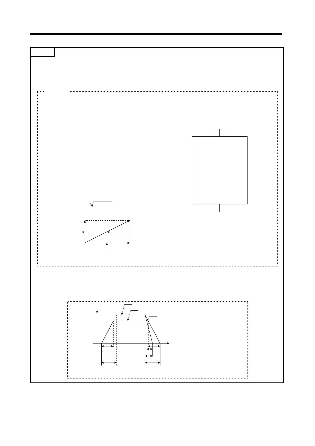
(1) Speed limit value and positioning speed
• The set speed limit value applies to the long-axis speed.
• Note that the combined speed may exceed the speed limit value if long-axis speed designation is
used.
During 2-axes linear interpolation with the following settings, the combined speed exceeds the
speed limit value.
Axis 1 travel value: 100 PLS
Axis 2 travel value: 200 PLS
Long-axis speed: 50 PLS/s
Speed limit value: 55 PLS /s
In this example, the reference axis is Axis 2, which has
the greatest travel value; therefore the set speed limit
value applies to Axis 2.
In this case, the positioning speed of each axis and
the combined speed are as follows:
Axis 1 positioning speed: (100/200)
×
50 = 25 PLS /s
Axis 2 positioning speed: 50 PLS /s
Combined speed:
25
2
+
50
2
= 55.9 PLS /s
[Program Example]
ABS-2
Axis 1, 10000
Axis 2, 15000
Axis 3, 5000
Axis 4, 20000
Long-axis speed 7000
<K 51>
(PLS)
(PLS)
(PLS)
(PLS)
(PLS/s)
Combined speed
Axis 1 positioning
speed
Axis 2 positioning speed
The combined speed exceeds the speed limit value setting of 55.
(2) Relationship between speed limit value, acceleration time, deceleration time, and rapid stop
deceleration time
• The real acceleration time, deceleration time, and rapid stop deceleration time are determined by
the long-axis speed setting.
Time
1)
Rapid stop genetrated
Positioning speed(long-axis speed)
Speed
3)
5)
6)
4)2)
Speed limit value
1) Real acceleration time
2) Set acceleratioon time
3) Real deceleration tim
4) Set deceleration time
5) Real rapid stop
deceleratioon time
6) Set rapid stop
deceleration time
Example
 Loading...