7. POSITIONING CONTROL
7 − 37
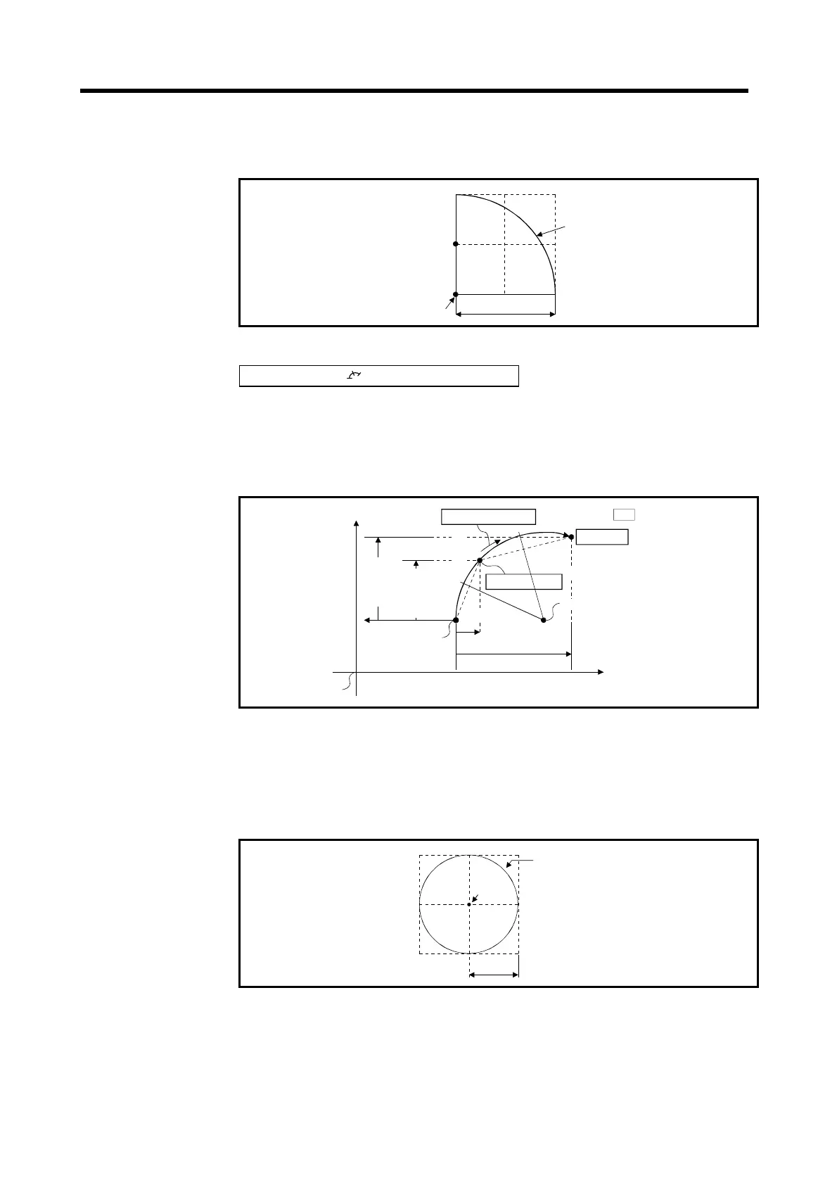
(3) The setting range for the end point address and auxiliary point address is –2
31
to +2
31
–1.
(4) The maximum arc radius is 2
32
−1.
Radius R
rc center point
2
31
-1
2
31
-1
Maximum ar
0
-2
31
Fig.7.10 Maximum Arc
Control with INC
(incremental method)
(1) Circular interpolation from the current stop address (pre-positioning address)
through the designated auxiliary point address to the end point address.
(2) The center of the arc is the point of intersection of the perpendicular bisectors
of the start point address (current stop address) to the auxiliary point address,
and the auxiliary point address to the end point address.
Forward direction
End point
: indicates set data
Travel value to
auxiliary point
X
2
X
1
Travel
value to
end
point
Y
2
Y
1
Start point
Home position
Auxliiary point
Positioning speed
Forward direction
Reverse direction
Travel value to end point
Center of arc
Travel
value to
auxiliary
point
Fig.7.11 Circular Interpolation Control by Incremental Method
(3) The setting range for the travel value to the end point address and auxiliary
point address is 0 to ±(2
31
–1).
(4) The maximum arc radius is 2
31
–1.
If the designated end point and auxiliary point result in a radius more than 2
31
–
1, an error occurs at the start and error code 107 is stored in the data register.
0
Radius R
Maximum arc
2
31
-1
31
-1
-2
31
Center
of arc
0
Fig.7.12 Maximum Arc
 Loading...