APPENDICES
APP − 37
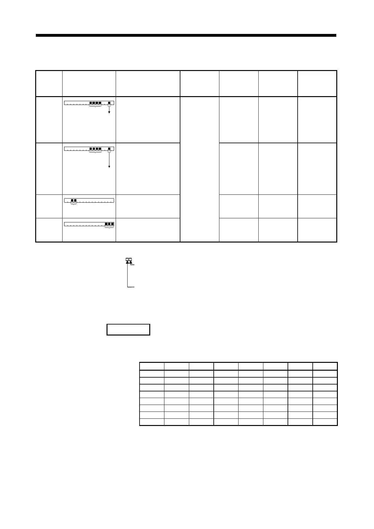
Table 2.15 LED Indications When Errors Occur at PCPU (Continued)
A173UHCPU
(S1) LED
Indication
!
!!
!:On
"
""
":Off
A273UHCPU Front LED
Indication
Error Cause Error Check Timing
Operation when
Error Occurs
Error Set Device Corrective Action
SV P()ERROR.
Indicates the "n"th serv
power supply module.
Servo error code
• Servo power supply module
(A230P)-detected servo error or
warning occurrence
• In that line, all
axes are put in
servo OFF status.
• Servo error
detection flag
(M2408+20n) ON
• Servo error code
device (D08+20n)
set
• Remove the error
cause and reset
the servo error. If
the servos of all
axes return to
normal after servo
error reset, the
LED indication
goes off.
SY P()ERR..S
Indicates the system error which
is independent of the servo
ower su
l
module line.
System error code (major
error) detected by servo
power supply module
Indicates the "n"th servo
power supply module.
• Servo power supply module
(A230P)-detected system error
(major error) occurrence
• In that line, all
axes are put in
servo OFF status.
• Major error
detection flag
(M2407+20n) ON
• Major error code
device (D07+20n)
set
• Remove the error
cause and give all-
axis servo ON
command. If all
axes are put in
servo ON status
properly, the LED
goes off.
!
UN I TSL ERROR
(Note) Base No. + slot No.
• Motion slot module fault detection
(During operation, the module
has come off or is coming off)
• Motion slot module
fault detection flag
(M2047) ON
• Switch power off
and load the
module properly.
!
PCPU WDT ERR.
PCPU WDT error code
• PCPU WDT error occurrence
Any time
• All axes stop
immediately.
• PCPU WDT error
flag (M9073) ON
• PCPU WDT error
cause (D9184) set
• Refer to Sections
3.3, 3.4.
(Note) Indicates the base number, slot number and slot information in error.
(SL
)
Slot Number in error
0: I/O slot 0
to
7: I/O slot 7
Base number in error
0: CPU base
1: Motion extension base 1
2: Motion extension base 2
3: Motion extension base 3
4: Motion extension base 4
REMARK
n in Table 2.15 (Error Set Device) is the value corresponding to the axis
number.
Axis No. n Axis No. n Axis No. n Axis No. n
1 0 9 8 17 16 25 24
2 1 10 9 18172625
3 2 11 10 19 18 27 26
4 3 12 11 20 19 28 27
5 4 13 12 21 20 29 28
6 5 14 13 22 21 30 29
7 6 15 14 23 22 31 30
8 7 16 15 24 23 32 31
Make the following calculation to find the device number corresponding to
each axis.
(Example) M2408+20n (Servo error detection flag) = M2408+20×31=M3028
D07+20n (Major error code device) = D07+20×31=D627
 Loading...