APPENDICES
APP − 48
Table 3.2 Special Register List (Continued)
Number Name Stored Data Explanation
D9125
to
D9132
Annunciator
detection
number
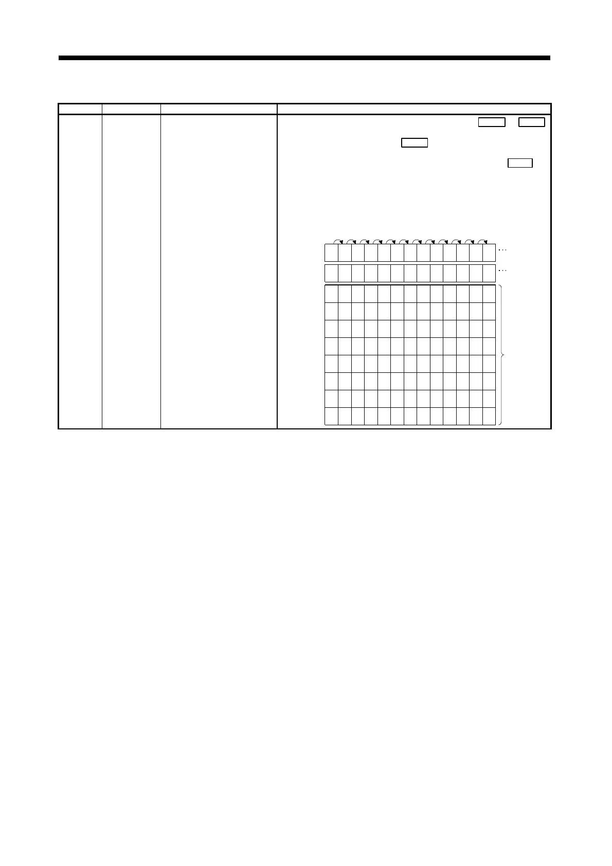
Annunciator detection number
!
When F numbers in the range F0 to 2047 are turned on by OUT F or SET F ,
they are entered in D9125 to D9132 in ascending order of register numbers.
An F number which is turned off by RST F
is erased from D9125 to D9132, and
the contents of the data registers following the one where the erased F number
was stored are each shifted to the preceding data register. When the LEDR
instruction is executed, the contents of D9125 to D9132 are shifted upward by
one.
(This may also be done with the INDICATOR RESET switch on the front of the
CPU module.)
When there are 8 annunciator detections, a 9th one is not stored in D9125 to
D9132 even if detected.
D9009
D9124
0
1
50
2
50
32
50 50
3
50
56
50
7
50
8
50
8
50
8
99
SET
F50
5050
0
4
SET
F25
SET
F99
RST
F25
SET
F15
SET
F70
SET
F65
SET
F38
SET
F110
SET
F151
SET
F210 LEDR
D9125
0
0 25259999 150
99 0 15 700
65070
65 380
38 1100
110 1101101510
151 151 2100
D9126
D9127
D9128
D9129
D9130
D9131
D9132
50 50 50 50 50 50 50 50 50 995050
000000000
00000000
0000000
000000
00000
00
99 99 99 99 99 99
38 38 38
65 65 65 65
70 70 70 70 70
15 15 15 15 15 15
detection
number
detection
quantity
detection
number
 Loading...