4. PARAMETERS FOR POSITIONING CONTROL
4 − 10
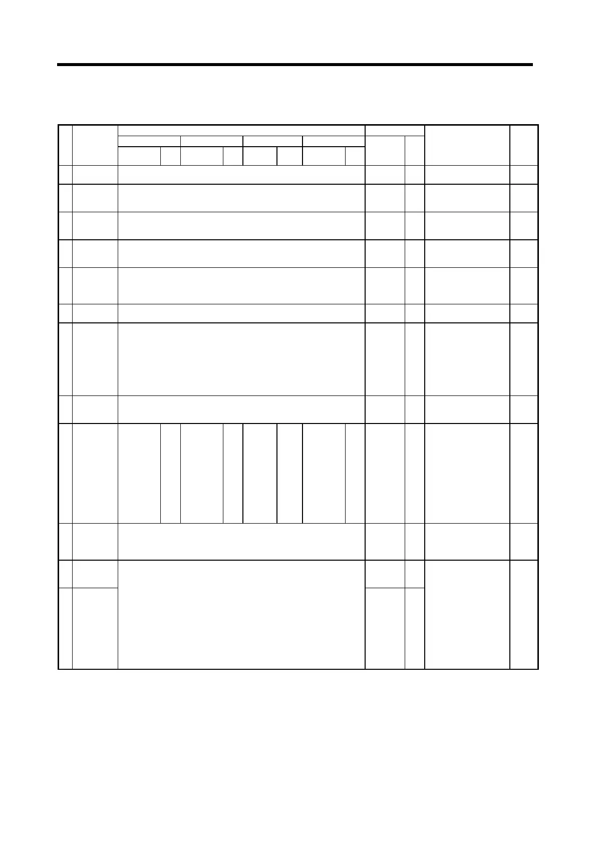
(2) Adjustment parameters
Table 4.5 Servo Parameter List (Adjustment Parameters)
Setting Range Default
mm inch degree PULSE
No. Item
Setting
Range
Units
Setting
Range
Units
Setting
Range
Units
Setting
Range
Units
Initial Value Units
Remarks
Expla-
natory
Section
1
Load inertia
ratio
0.0 to 100.0
3.0
(Note-1)
• Set the ratio of moment of
load inertia for the motor.
4.3.8
2
Position
control gain 1
Valid range 4 to 1000 rad/s Setting range 1 to 9999 rad/s 70 rad/s
• Set to increase the follow-
up with respect to the
position command.
4.3.3
3
Speed control
gain 1
Valid range 20 to 5000 rad/s Setting range 1 to 9999 rad/s 1200 rad/s
• Set to increase the follow-
up with respect to the
speed command.
4.3.4
4
Position
control gain 2
Valid range 10 to 500 rad/s Setting range 1 to 9999 rad/s 25 rad/s
• Set to increase the position
response with respect to
load disturbance.
4.3.3
5
Speed control
gain 2
Valid range 20 to 5000 rad/s Setting range 1 to 9999 rad/s 600 rad/s
• Set when vibration is
generated, for example in
machines with a large
backlash.
4.3.4
6
Speed integral
compensation
Valid range 1 to 1000 rms Setting range 1 to 9999 rad/s 20 ms
• Set the time constant for
integral compensation.
4.3.5
7 Notch filter
0: Not used
1: 1125
2: 750
3: 562
4: 450
5: 375
6: 321
7: 281
0Hz
• Set the frequency for the
notch filter.
4.3.11
8
Feed forward
gain
0 to 100%
0: Feed forward control is not executed.
0%
• Set the feed forward
coefficient used in
positioning control.
4.3.7
9
In-position
range
(Note-2)
0.1 to
214748364.7
µ
m
0.00001
to
21474.83647
inch
0.00001
to
359.99999
degree
1 to
2147483647
PLS 100 PLS
• Sets the quantity of droop
pulses in the deviation
counter.
• The in-position signal is ON
when the number of droop
pulses is within the set
range. The expression
below shows the setting
range.
1 ≤ (in-position range) ×
AP/AL ! AM ≤ 32767
4.3.6
10
Electromag-
netic brake
sequence
0 to 1000 ms 100 ms
• Set the time delay between
actuation of the
electromagnetic brake and
base disconnection.
4.3.12
11
Monitor output
mode
(monitor 1)
0
12
Monitor output
mode
(monitor 2)
(MR-H-BN)
0: Speed (±)
1: Torque (±)
2: Speed (+)
3: Torque (+)
4: Current command output
5: Command F∆T
6: Droop pulse 1/1
7: Droop pulse 1/4
8: Droop pulse 1/16
9: Droop pulse 1/32
(MR-J2S-B/MR-J2-B)
0: Speed (±)
1: Torque (±)
2: Speed (+)
3: Torque (+)
4: Current command output
5: Command F∆T
6: Droop pulse 1/1
7: Droop pulse 1/16
8: Droop pulse 1/64
9: Droop pulse 1/256
10: Droop pulse 1/1024
1
• Set the monitor items
output as analog outputs in
real time.
4.3.13
(Note-1) : For MR-J2S-B/MR-J2-B, the default is "7.0".
(Note-2) : The display of the possible setting range differs according to the electronic gear value.
 Loading...