18
FIELD WIRING
7
L
N
S1
S2
S3
S1
S2
S3
TB1
L
N
ECB1
L
N
Earth
leakage
circuit
breaker
*1, *2
Outdoor unit
Power supply
~/N 230 V 50 Hz
Wiring
circuit
breaker or
Isolating
switch
To control
board
For
booster
heater
Hydrobox
Wiring
circuit
breaker or
Isolating
switch
Power supply
~/N 230 V 50 Hz
L1
L2
S1
S2
S3
S1
S2
S3
TB1
L2
L3
ECB1
N
L3
L1
N
L
Earth
leakage
circuit
breaker
*1, *2
Outdoor unit
Power supply
3~ 400 V 50 Hz (E***-YM9*E)
3~ 230 V 50 Hz (E***-TM9*E)
Wiring
circuit
breaker or
Isolating
switch
To control
board
For
booster
heater
Hydrobox
Wiring
circuit
breaker or
Isolating
switch
Power supply
3N~ 400 V 50 Hz
Hydrobox powered via outdoor unit
(If you want to use independent source, go to the Mitsubishi website.)
PXZ model is not available.
The model is Hydrobox powered by independent source ONLY.
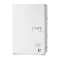
<1 phase>
Ax label A that is included with the manuals near each wiring diagram for hydrobox and outdoor units.
<Figure 7.1>
Electrical connections 1 phase
Description Power supply Capacity Breaker Wiring
Booster heater ~/N 230 V 50 Hz
2 kW 16 A
*2 2.5 mm²
6 kW 32 A
*2 6.0 mm²
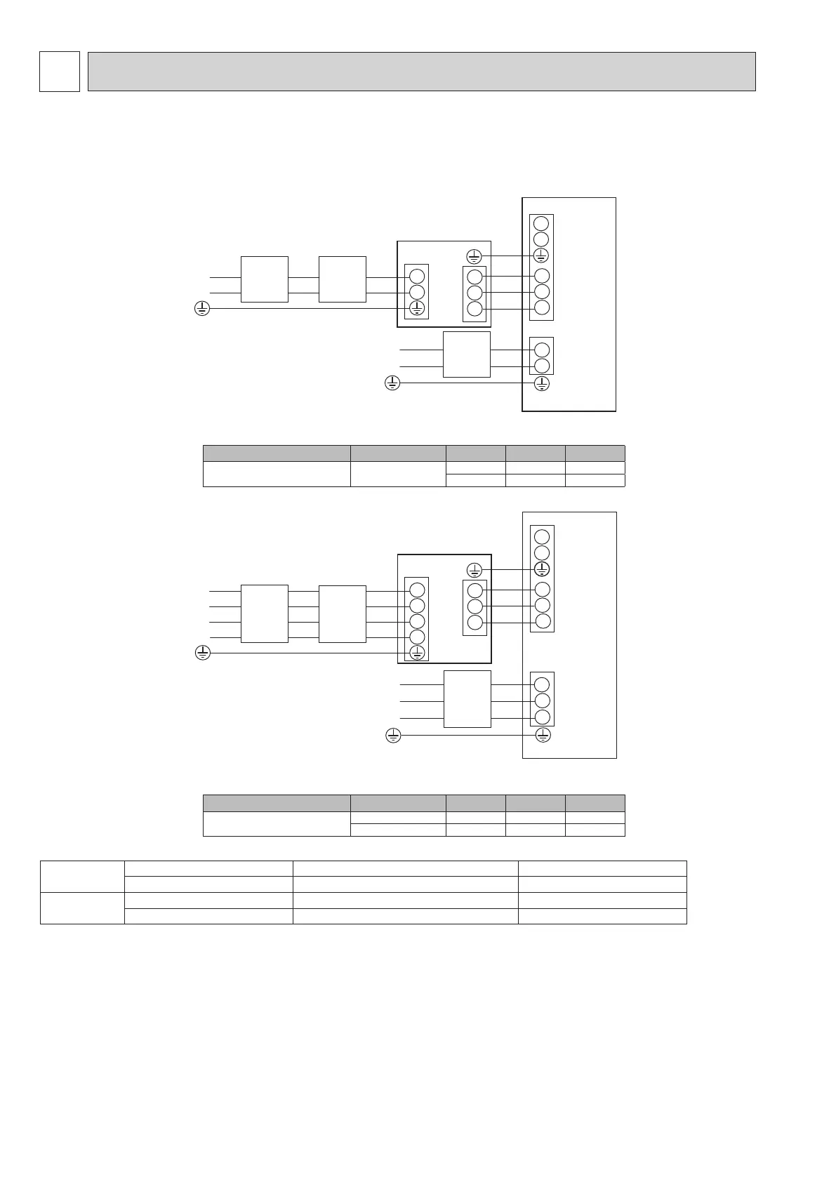
<Figure 7.2>
Electrical connections 3 phase
Description Power supply Capacity Breaker Wiring
Booster heater
3~ 400 V 50 Hz 9 kW 16 A
*2 2.5 mm²
3~ 230 V 50 Hz 9 kW 32 A
*2 6.0 mm²
Wiring No.
× size (mm²)
Hydrobox - Outdoor unit 3 × 1.5 (polar)
*3
3 × 4 (polar)
*4
Hydrobox - Outdoor unit earth 1 × Min. 1.5
*3
1 × Min. 2.5
*5
Circuit rating
Hydrobox - Outdoor unit S1 - S2
*6
230 VAC 230 VAC
Hydrobox - Outdoor unit S2 - S3
*6
24 VDC 24 VDC
*1. If the installed earth leakage circuit breaker does not have an over-current protection function, install a breaker with that function along the same power line.
*2. A breaker with at least 3.0 mm contact separation in each pole shall be provided. Use earth leakage breaker (NV).
The breaker shall be provided to ensure disconnection of all active phase conductors of the supply.
*3. Max. 45 m
If 2.5 mm² used, Max. 50 m
If 2.5 mm² used and S3 separated, Max. 80 m
*4. Max. 50 m
If 6 mm² used, Max. 80 m
*5. If S3 separated, Max. 80 m
*6. The values given in the table above are not always measured against the ground value.
Notes: 1. Wiring size must comply with the applicable local and national codes.
2. Indoor unit/outdoor unit connecting cords shall not be lighter than polychloroprene sheathed exible cord. (Design 60245 IEC 57)
Indoor unit power supply cords shall not be lighter than polychloroprene sheathed exible cord. (Design 60227 IEC 53)
3. Install an earth line longer than power cables.
4. Please keep enough output capacity of power supply for each heater. Insucient power supply capacity might cause chattering.
<3 phase>
Ax label A that is included with the manuals near each wiring diagram for hydrobox and outdoor units.
<E*SD/ERSF/ERSC/ERPX series> <ERSE series>
OCH815A
 Loading...