8
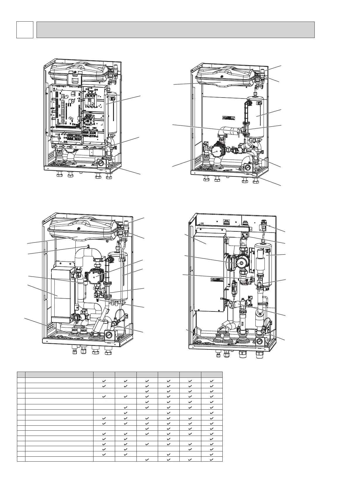
PART NAMES AND FUNCTIONS
4
<Figure 4.3>
<Figure 4.4>
<E*S*-*M*E> (Split model system)
7
11
8
13
3
4
5
16
12
<ERSE-*M*EE> (Split model system)
15
14
3
5
14
7
8
11
4
10
6
6
1
2
11
9
8
14
12
10
4
7
<ERPX-*M*E> (Packaged model system)
<Figure 4.1> <Figure 4.2>
6
13
15
No. Part name
ERPX-ME ERPX-*M*E EHSD-MEE EHSD-*M*E ERS*-MEE ERS*-*M*(E)E
1 Control and electrical box
2 Main remote controller
3 Plate heat exchanger (Refrigerant - Water)
- -
4 Water circulation pump 1
5 Air vent (manual)
- -
6 Drain cock (Primary circuit)
-
7 Booster heater 1, 2
- - -
8 Flow sensor
9 Manometer
10 Pressure relief valve (3 bar)
- -
11 Automatic air vent
12 Expansion vessel
- -
*1
13 Magnetic lter
14 Drain pan
- -
15 Pressure relief valve (5 bar)
- -
*1
16 Pressure sensor
- -
*2 *2
<Table 4.1>
Note:
For installation of all
E***-*M*EE models, make
sure to install a suitably
sized primary-side expan
-
sion vessel. (See gure 8.1
-8.2 for further guidance)
*1 ERSE-YM9EE is not
included.
*2 ERSC-*, ERSE-* is not
included.
OCH815A