9
OUTLINES AND DIMENSIONS
5
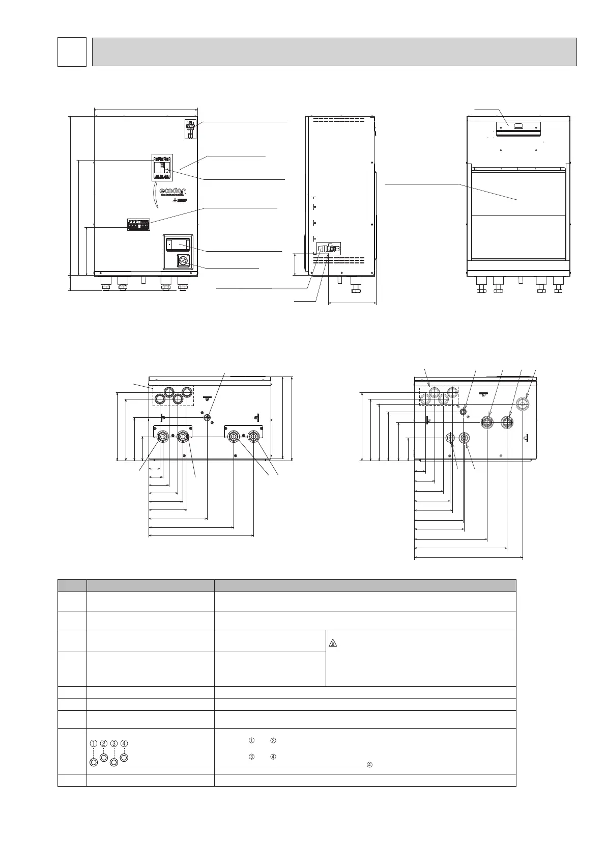
5-1. Technical Drawings
<Unit: mm>
530
800
578
242
75±5
(242)
110
AUTOMATIC AIR VENT
FRONT PANEL
EARTH LEAKAGE
CIRCUIT BREAKER
TERMINAL BLOCK
MAIN CONTROLLER
MANOMETER
PRESSURE RELIEF VALVE
G1/2
BACK PANEL SUPPORT
HOOK
<Front> <Side> <Rear>
I
H
291
263
183
103
F
48
60
86
124
145
163
248
361
446
(348)
357
E
B
A
<View from below>
<ERPX>
(Packaged model system for heating and cooling)
Letter Pipe description Connection size/type
A
Space heating/Indirect DHW tank
(primary) RETURN connection
G1 (EHSD/ERSD/ERSC/ERSF/ERPX-*)
B
Space heating/Indirect DHW tank
(primary) FLOW connection
G1 (EHSD/ERSD/ERSC/ERSF/ERPX-*)
C
Refrigerant (Liquid)
6.35 mm/Flare (E*SD/F-*)
9.52 mm/Flare (E*SC-*)
Warning
• Refrigerant pipes connection shall be accessible for
maintenance purposes.
• In case of reconnecting the refrigerant pipes after
detaching, make the flared part of pipe re-fabricated.
D
Refrigerant (Gas)
12.7 mm/Flare (E*SD-*)
12.7 or 15.88mm/Flare (ERSF-*)
15.88 mm/Flare (E*SC-*)
E
Flow connection FROM heat pump
G1 (ERPX-*)
F
Return connection TO heat pump
G1 (ERPX-*)
G
Discharge pipe (by installer) from
pressure relief valve
G1/2 (valve port within hydrobox casing)
H
Electrical cable inlets
For inlets and , run high-voltage wires including power cable, indoor-outdoor cable, and
external output wires.
For inlets
and , run low-voltage wires including external input wires and thermistor wires.
For a wireless receiver (option) cable, use inlet
.
I Drain socket Outside diameter 20 mm (EHSD-* not included.)
<Table 5.1>
<ERS*> (Split model system for heating and cooling)
(Except for ERSE series)
<View from below>
153
213
48
86
124
163
208
310
395
98
164
209
242
461
263
B
A
D
C
OCH815A