14
FL remote communication specification
2.5 FL remote communication specification
2.6 Node address setting
Set a node address between "1 to 64" using node address switches. (Refer to page 1.)
The setting is applied when the power turns OFF once, then ON again.
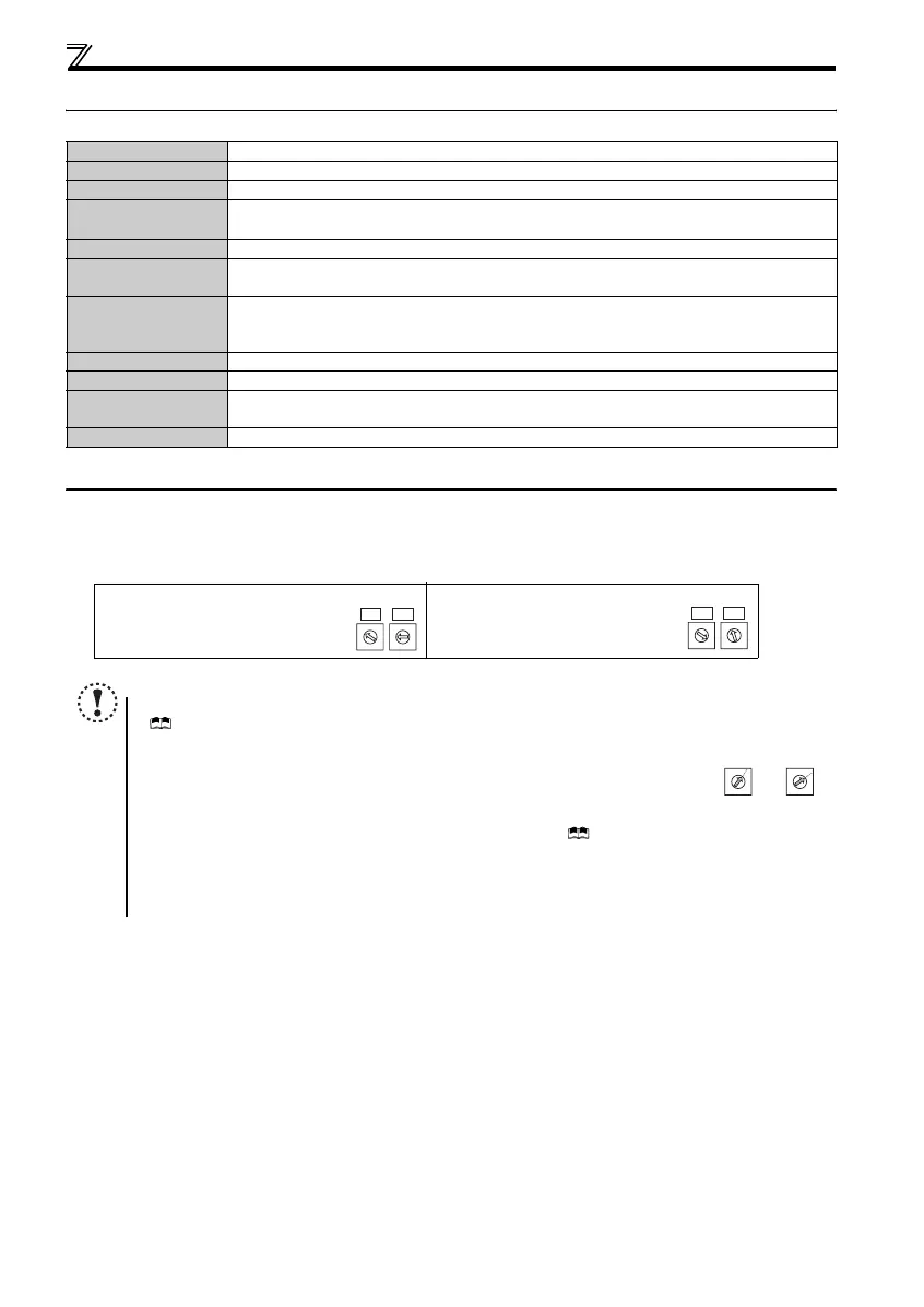
Set the arrow (×) of the corresponding switches to the number to set a desired address.
z
Setting example
Type Built-in to an inverter, RJ-45 connector connection method
Power supply Supplied from the inverter or the 24VDC external power supply
Connection cable FL-net dedicated cable (Refer to page 15)
Maximum number of
connectable inverters
64 units maximum
Communication speed
Auto negotiation (auto detection) (10Mbps/100Mbps)
Topology
y Star (connection with a hub in the center)
y Star bus (connection with multiple hubs)
Communication
distance
y Between node ⇔ hub: 100m maximum (Node indicate master and inverters.)
y Between hubs: 100m maximum
y Overall length: 2000m maximum
Electrical interface
Conforms to IEEE802.3u (conforms to CSMA/CD)
Transmission protocol
FL remote
Node address setting
Can be set with node address switch.
Reflected to IP address as well. (192.168.250. node address)
I/O points
Input 64 points, output 64 points
Node address 1:
Set the "×" of X10(SW2) to "0" and the
"×" of X1(SW1) to "1."
Node address 26:
Set the "×" of X10(SW2) to "2" and the
"×" of X1(SW1) to "6."
NOTE
y Always remove the front cover before setting a node address with node address switches.
( Refer to Chapter 1 of the Instruction Manual (Applied))
y
Set the node address switch to the switch number position correctly. If the switch is set
between numbers, normal data communication can not be established.
y If the node address switch is set to a value other than "1 to 64", it is invalid due to outside of setting range. In this
case, DEV LED is lit red and E.OPT appears on the operation panel. ( Refer to Chapter 6 of the Instruction Manual
(Applied)
y You cannot set the same node address to other devices on the network. (Doing so disables proper communication.)
y
Set the inverter node address before switching ON the inverter and do not change the setting while power is
ON. Otherwise you may get an electric shock.
0
9
8
7
6
5
4
3
2
1
0
9
8
7
6
5
4
3
2
1
X1
X10
0
9
8
7
6
5
4
3
2
1
0
9
8
7
6
5
4
3
2
1
X1
X10
0
9
8
7
6
5
4
3
2
1
0
9
8
7
6
5
4
3
2
1
Good
example
Bad
example
 Loading...