6
Wiring
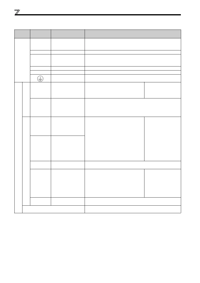
2.3.2 Terminal specifications
* For more details, refer to the Safety stop function instruction manual (BCN-A211508-004). (Refer to the front cover for how to obtain the manual.)
Type
Termin al
Symbol
Terminal Name Description
Main circuit
R/L1,
S/L2,
T/L3
AC power input Connect to the commercial power supply.
U, V, W Inverter output Connect a three-phase squirrel-cage motor.
P/+, PR Brake resistor connection
Connect a brake resistor (FR-ABR, MRS type, MYS type) across terminals P/+
and PR.
(The brake resistor cannot be connected to the 0.1K or 0.2K.)
P/+, N/- Brake unit connection Connect the brake unit (FR-BU2).
P/+, P1 DC reactor connection Remove the jumper across terminals P/+ and P1 and connect a DC reactor.
Earth (Ground) For earthing (grounding) the inverter chassis. Must be earthed (grounded).
Control circuit
24V external power supply
+24
24V external power
supply
Even when the main circuit power supply is
OFF, FL-net communication continues with the
input from the 24V external power supply.
Input voltage
23.5 to 26.5VDC
Input current
0.7A or less
SD
24V external power
supply common terminal
Common terminal for the terminal +24
Safety stop function *
S1
Safety stop input
(Channel 1)
Terminal S1/S2 are safety stop signals for use
with in conjunction with an approved external
safety unit. Both terminal S1/S2 must be used in
dual channel form. Inverter output is shutoff
depending on shorting/opening between S1 and
PC, S2 and PC.
In the initial status, terminal S1 and S2 are
shorted with terminal PC by shorting wire.
Remove the shorting wire and connect the
safety relay module when using the safety stop
function.
Input resistance 4.7kΩ
Voltage when contacts are
open
21 to 26VDC
When contacts are short-
circuited
4 to 6mADC
S2
Safety stop input
(Channel 2)
PC
Safety stop input terminal
common
Common terminal for safety stop input terminals S1 and S2.
Y0
Open collector output Y0
(safety monitor output 2)
This terminal is switched to Low during the
operation with no internal safety circuit fault
(E.SAF, E.6, E.7, E.CPU). It is switched to High
in operation statuses other than above.
(Low indicates that the open collector output
transistor is ON (conducts). High indicates that
the transistor is OFF (does not conduct).)
Permissible load 24VDC
(maximum 27VDC) 0.1A
(a voltage drop is 3.4V
maximum when the signal is
ON)
SE
Open collector output
common
Common terminal of terminal Y0.
FL remote communication connector
With the FL remote communication connector, FL remote communication can
be performed.
 Loading...