EasyManua.ls Logo

Mitsubishi Electric TRANE TPLFYP015FM140A User Manual

Mitsubishi Electric TRANE TPLFYP015FM140A
40 pages
To Next Page IconTo Next Page
Page #1 background imageLoading...
Page #1 background image
Indoor unit
[Model Name]
TPLFYP005FM140A
TPLFYP008FM140A
TPLFYP012FM140A
TPLFYP015FM140A
TPLFYP018FM140A
R410A
TECHNICAL & SERVICE MANUAL
April 2019
No. TCHT003
INDOOR UNIT


CONTENTS
1. SAFETY PRECAUTION
..........................
2
2. PARTS NAMES AND FUNCTIONS
........
4
3. SPECIFICATIONS
.................................
13
4. 4-WAY AIR FLOW SYSTEM
.................
15
5. OUTLINES AND DIMENSIONS
............
17
6. WIRING DIAGRAM
...............................
18
7.
REFRIGERANT SYSTEM DIAGRAM
......
19
8. MICROPROCESSOR CONTROL
..........
20
9. TROUBLESHOOTING
..........................
27
10. DISASSEMBLY PROCEDURE
........... 35
PARTS CATALOG (TCBT003)
Question and Answer IconNeed help?

Do you have a question about the Mitsubishi Electric TRANE TPLFYP015FM140A and is the answer not in the manual?

Mitsubishi Electric TRANE TPLFYP015FM140A Specifications

General IconGeneral
BrandMitsubishi Electric
ModelTRANE TPLFYP015FM140A
CategoryAir Conditioner
LanguageEnglish

Summary

1 SAFETY PRECAUTION

R410A Refrigerant Handling and System Safety

Covers general safety, piping, oil, charging, tools, and ventilation for R410A.

Service Cautions and Procedures

Precautions for service, refrigerant charging, and required service tools.

3 SPECIFICATIONS

3-1. SPECIFICATIONS - Indoor Unit Electrical and Physical Data

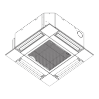
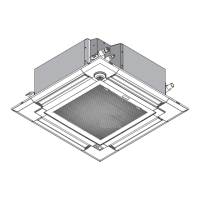
Technical specifications for indoor units, including dimensions, weight, and capacities.

6 WIRING DIAGRAM

Indoor Unit Wiring Diagram and Component Legend

Wiring diagram for indoor units and a legend of components.

7 REFRIGERANT SYSTEM DIAGRAM

Refrigerant Circuit Diagram and Pipe Specifications

Diagram of the refrigerant circuit and specifications for gas and liquid pipes.

8 MICROPROCESSOR CONTROL

8-1. COOL OPERATION

Control details and operation procedures for the cooling mode.

8-2. DRY OPERATION

Control details and operation procedures for the dry mode.

8-3. FAN OPERATION

Control details and operation procedures for fan-only mode.

8-4. HEAT OPERATION

Control details and operation procedures for the heating mode.

9 TROUBLESHOOTING

9-1. COUNTERMEASURES FOR ERROR DURING TEST RUN

List of error codes, troubles, and countermeasures for test run issues.

9-2. HOW TO CHECK THE PARTS

Procedures for checking the resistance and functionality of various parts.

Linear Expansion Valve Output Pulse and Troubleshooting

Details on output pulse signals, valve operation, and troubleshooting for linear expansion valves.

9-2-3. DC Fan Motor (Fan Motor/Indoor Controller Board) Check

Method for checking DC fan motor and indoor controller board for issues.

9 FUNCTION OF DIP SWITCH

9-4. TEST POINT DIAGRAM

Indoor Controller Board Test Points

Diagram showing test points on the indoor controller board for diagnostics.

Related product manuals