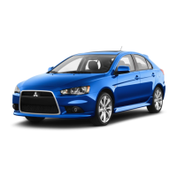
No. Symbol Electrical system
Ca-
pacity
26 Rear window wiper 15 A
27 — — —
28 — — —
29 — — —
30 — — —
31 Hazard warning flasher 10 A
32 — — —
33 Door locks 15 A
34 Front fog lamps 15 A
35 Headlamp low beam (left) 10 A
36
Headlamp low beam
(right)
10 A
37 Reversing lamp 7.5 A
38 Engine control 7.5 A
39 Ignition coil 10 A
40 Gauge 7.5 A
41 Relay 7.5 A
42 STOP Stop lamps 15 A
43 Air conditioning 7.5 A
44 — — —
l
Some fuses may not be installed on your ve-
hicle, depending on the vehicle model or spec-
ifications.
l
The table above shows the main equipment
corresponding to each fuse.
Identification of fuse
Capacity Colour
7.5 A Brown
10 A Red
15 A Blue
20 A Yellow
30 A Green
40 A
Orange (fuse type)/Green (fusi-
ble link type)
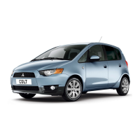
Fuse replacement
1. Before replacing a fuse, always turn off the
electrical circuit concerned and place the ig-
nition switch in the “LOCK” position.
2. Remove the fuse puller from the cover. (Re-
fer to “To remove the cover” on pages 8-22,
8-22.)
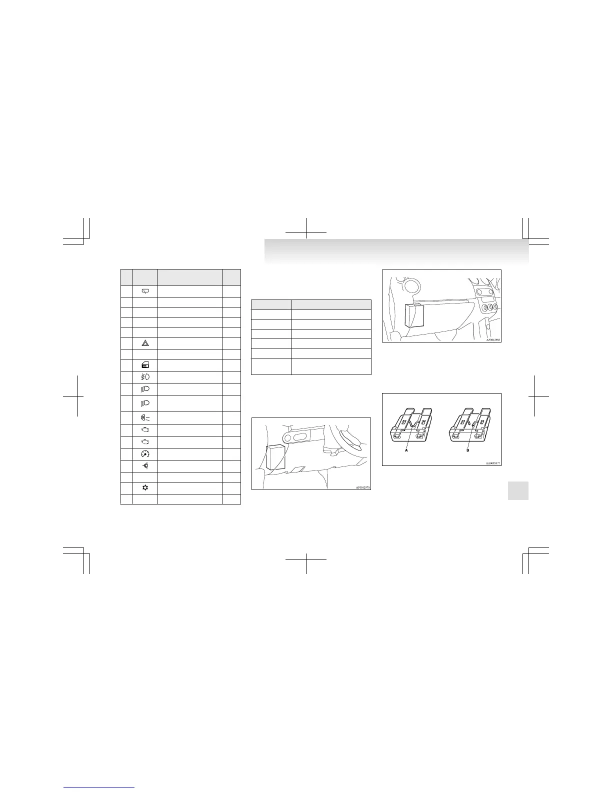
3. Referring to the fuse load capacity table,
check the fuse pertaining to the problem.
A- Fuse is OK
B- Blown fuse
NOTE
l
If any system does not function but the fuse
corresponding to that system is normal, there
may be a fault in the system elsewhere. We
recommend you to have your vehicle checked.
Maintenance
8-21
8
 Loading...