Do you have a question about the Mitsubishi MELFA RV-2SD-S16 and is the answer not in the manual?
| Payload Capacity | 2 kg |
|---|---|
| Repeatability | ±0.02 mm |
| Degrees of Freedom | 6 |
| Installation | Floor, Wall, Ceiling |
| Protection class | IP40 |
| Axis 1 rotation | ±170° |
| Axis 6 turn | ± 360° |
| Axis 2 arm | +155° to -95° |
Details the components included as standard in the robot's structure.
Explains how to identify the robot's model type based on its nomenclature.
Details differences in robots prepared with CE marking specifications.
Describes how to set the display language to English for indirect export.
Information on instruction manuals supplied on CD-ROM, including Safety Manual.
Lists the components included in the structural equipment for the robot arm.
Provides a list of all optional equipment and special specifications available.
Details the standard specifications of the robot arm, including type, axes, and dimensions.
Defines key specifications like pose repeatability, rated load, and protection.
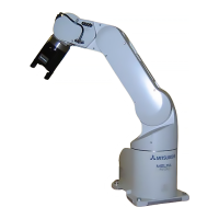
Illustrates and names the various parts of the robot arm.
Shows the external dimensions and operating range diagrams for the robot arm.
Details wiring and piping configurations for hands and tools attached to the robot arm.
Explains the various optional equipment available for the robot to enhance functionality.
Provides information on robot overhaul, including recommended intervals and procedures.
Lists consumable parts required for robot arm maintenance and their suppliers.
Details the standard specifications of the CR1DA-700 series controller.
Identifies and explains the various parts and controls on the controller unit.
Provides dimensions and installation guidelines for the controller unit.
Describes the types of external inputs and outputs available for robot control.
Explains the functions of dedicated input/output signals for robot operations.
Details wiring for emergency stop, special stop, door switch, and enabling device.
Explains the controller's interface for controlling additional axes.
Describes the AXMC output for synchronizing additional axis servo power.
Lists and describes the various optional components available for the controller.
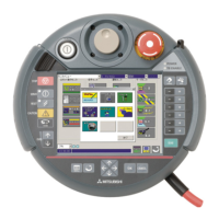
Details the teaching pendant (T/B) for program creation, editing, and robot control.
Explains the interface required for using the robot arm's hand output signals.
Describes the parallel I/O interface for expanding external inputs and outputs.
Details the dedicated cable for connecting external devices to the parallel I/O interface.
Explains the parallel I/O unit for expanding external inputs and outputs.
Details the dedicated cable for connecting external devices to the parallel I/O unit.
Describes the RS-232 interface cable for connecting the controller to a personal computer.
Explains the CC-Link interface for adding bit data and CC-Link field network function.
Describes the extension memory cassette for increasing robot program teaching points.
Introduces software for robot specification study, design, startup, and maintenance.
Information on the printed version of the CD-ROM instruction manual.
Lists consumable parts for the controller and their suppliers.
Lists available new functions and commands in MELFA-BASIC V.
Details important parameters for robot configuration and operation.
Describes the contents and purposes of associated instruction manuals.
General safety guidelines and self-diagnosis stop functions for robot operation.
Recommends suitable installation environments and precautions to avoid damage.
Provides essential handling precautions for the robot arm and its components.
Provides supplementary materials and discussion on robot specifications.

