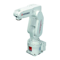
Do you have a question about the Mitsubishi MELFA RV-2SDB-S15 and is the answer not in the manual?
| Model | RV-2SDB-S15 |
|---|---|
| Manufacturer | Mitsubishi Electric |
| Category | Robotics |
| Number of Axes | 6 |
| Degrees of Freedom | 6 |
| Payload Capacity | 2 kg |
| Reach | 504 mm |
| Repeatability | ±0.02 mm |
| Installation | Floor, Ceiling, Wall |
| Type | Robot Arm |
| Power Supply | 200-240V AC |
All teaching work must be carried out by an operator who has received special training.
Prepare a work plan related to the methods and procedures of operating the robot.
Prepare a device that allows operation to be stopped immediately during teaching work.
Place a sign indicating that teaching work is in progress on the start switch, etc.
Provide a fence or enclosure during operation to prevent contact of the operator and robot.
Establish a set signaling method to the related operators for starting work.
Turn the power OFF during maintenance work. Place a sign indicating that maintenance work is in progress.
Inspect the robot, emergency stop switch and other related devices, etc., before starting work.
Details on the components included in the structural equipment.
Explanation of the model type name format for identifying the robot series and specifications.
List of structural equipment for the robot arm and controller.
List of all Optional equipments and special specifications.
Table detailing the standard specifications of the robot arm.
Definitions of specifications like repeatability, load capacity, and protection.
Robot's mass capacity, considering tooling and eccentric loads.
Robot arm protection specifications that comply with IEC Standards.
Diagrams showing the outside dimensions and operating range of the robot.
Details on wiring and piping configurations for the robot arm's tooling.
Description of various options available for the robot arm.
Table detailing the standard specifications of the CR1DA-700 series controller.
Detailed specifications of the CR1DA-700 series controller.
Controller protection method and operating supply specifications.
Diagrams and descriptions of the controller's parts and connectors.
Dimensions and installation requirements for the controller.
Overview of external input and output signals for the controller.
List and functions of dedicated input/output signals.
Wiring and functions for emergency stop, special stop, door switch, and enabling device.
Procedure for connecting external emergency stop switches.
Electric specifications and connection for the special stop input (SKIP).
Functionality of the door switch for safety fence interlocks.
Functionality and use of the enabling device for safety.
General safety measures and self-diagnosis stop functions for robot operation.

