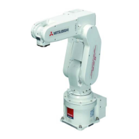
Do you have a question about the Mitsubishi MELFA SD Series and is the answer not in the manual?
All teaching work must be carried out by a trained operator.
Prepare a work plan for operating the robot and handling errors.
Prepare a device to stop operation immediately during teaching.
Provide a fence or enclosure to prevent contact between operator and robot.
Inspect robot, emergency stop switch, and related devices before starting work.
Operate within specified environmental conditions to avoid faults.
Use correct posture to prevent injuries or faults from dropping.
Ensure workpiece weight does not exceed rated load or tolerable torque.
Properly install tools and grasp workpieces to prevent injury or damage.
Grounding prevents malfunctioning and electric shock.
Ensure safety fence door locks or stops robot when opened during operation.
Do not modify or use non-designated parts to prevent faults.
Do not turn off controller main power during operation to maintain accuracy.
Do not turn off power while rewriting internal information to prevent data damage.
Use confirmed network equipment; implement noise measures if necessary.
Install an earth leakage breaker for leakage protection.
Inclusion of EC Declaration of Conformity documents.
Changes to the controller's external dimensions.
Correction of signal assignments for I/O interfaces.
Explanation of KC mark specification controller added.
Details of the robot's structural components and standard enclosures.
How to identify the robot model by its type name.
Differences and type names for CE marking specifications.
Details about supplied instruction manuals on CD-ROM.
List of structural equipment for the robot arm.
Devices that can be installed on the controller and their connections.
List of optional equipment and special specifications.
Detailed technical specifications of the robot arm.
Explanation of key specification definitions.
Details on mass capacity and related design considerations.
Information on robot arm protection specifications and applicable fields.
Diagram and identification of major robot arm parts.
Diagrams showing external dimensions and operating ranges.
Information on wiring and piping for hands.
Details on internal air piping for the robot.
Wiring for pneumatic hand output signals.
Wiring for hand check input signals.
System diagrams for hand wiring and piping.
Electrical specifications for hand input and output circuits.
Example of pneumatic supply circuitry for the hand.
Overview of available robot options.
Details on machine cable extension order types, outline, and configuration.
Instructions for fixing flexible cables.
Information on changing the operating range using stoppers.
Order types, outline, configuration, and specifications for solenoid valve sets.
Order type, outline, configuration, and specifications for hand input cables.
Order type, outline, configuration, and specifications for hand output cables.
Order type, outline, configuration, and specifications for hand curl tubes.
Information on robot overhaul procedures and intervals.
List of consumable parts for the robot arm.
Detailed standard specifications for the CR1DA-700 series controller.
Protection methods and operating supply details for the controller.
Diagram and identification of controller parts.
Method for locking the power switch using a padlock.
Identification of connectors and terminals on the rear of the CR1DA-771 controller.
Identification of connectors and terminals on the rear of CR1DA-771-S15/S16 controllers.
Diagrams showing the outside dimensions of the controller.
External dimensions for the CR1DA-771-S15 controller.
Requirements for installing the controller, including clearances.
Details on cable entry points and dimensions for the controller.
Overview of external input/output types for robot control.
Details on dedicated input/output signals and their functions.
Wiring for external emergency stop, special stop, door switch, and enabling device.
Electric specifications and internal circuit for the special stop input.
Functionality of the door switch for safety fence interlocks.
Function and usage of the enabling device for safety.
Switch settings for various operations like automatic, jog, and brake release.
Information on controlling additional axes using the controller.
Using AXMC for synchronizing servo ON/OFF status with additional axes.
Overview of available controller options.
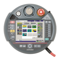
Order types, outline, configuration, and specifications for teaching pendants.
Layout of keys and explanation of main functions on the teaching pendant.
Interface required for robot arm's hand output signals.
Information on the parallel I/O interface for expanding external I/Os.
Details on order types, configuration, specifications, and pin numbers for external I/O cables.
Information on parallel I/O units for expanding external inputs and outputs.
Installation method and dimensions for the parallel I/O unit.
Connection method for expansion parallel I/O units.
Pin arrangement of connectors for the parallel I/O unit.
Details on order types, configuration, specifications, and pin numbers for external I/O cables.
Information on the CC-Link interface option for communication.
Detailed specifications for the CC-Link interface.
Information on the extension memory cassette for increasing teaching points.
Details on the RT ToolBox2 software for PC functions.
Features and functions of RT ToolBox2 software.
Details on the bound instruction manuals provided.
List of consumable parts for the controller.
List of available commands in MELFA-BASIC V.
List of main parameters for robot configuration and operation.
Overview of the various instruction manuals provided with the product.
General safety measures for industrial robot usage.
External I/O signals for implementing safety measures.
Safety precautions for robot installation, operation, and handling.
Safety measures to be taken during automatic robot operation.
Safety measures to be observed during robot teaching operations.
Safety measures for maintenance, inspection, and repair work.
Wiring examples for emergency stop and other safety circuits.
Supplementary explanation for external emergency stop connections.
Recommended installation locations and environmental conditions for optimal operation.
Important handling precautions for the robot arm and controller.
Material related to specifications and robot selection.
| Brand | Mitsubishi |
|---|---|
| Model | MELFA SD Series |
| Category | Robotics |
| Language | English |


