3-87 CC-Link interface
3 Controller
(8) CC-Link interface
■ Order type: ● 2D-TZ576
■ Outline
The CC-Link interface is the optioninterface to not only add bit data to the robot
controller. but also to add CC-Link field network function that allows cyclic
transmission of word data.
■ Configuration
Table 3-34 : Configuration device
Table 3-35 : Procured by the customer
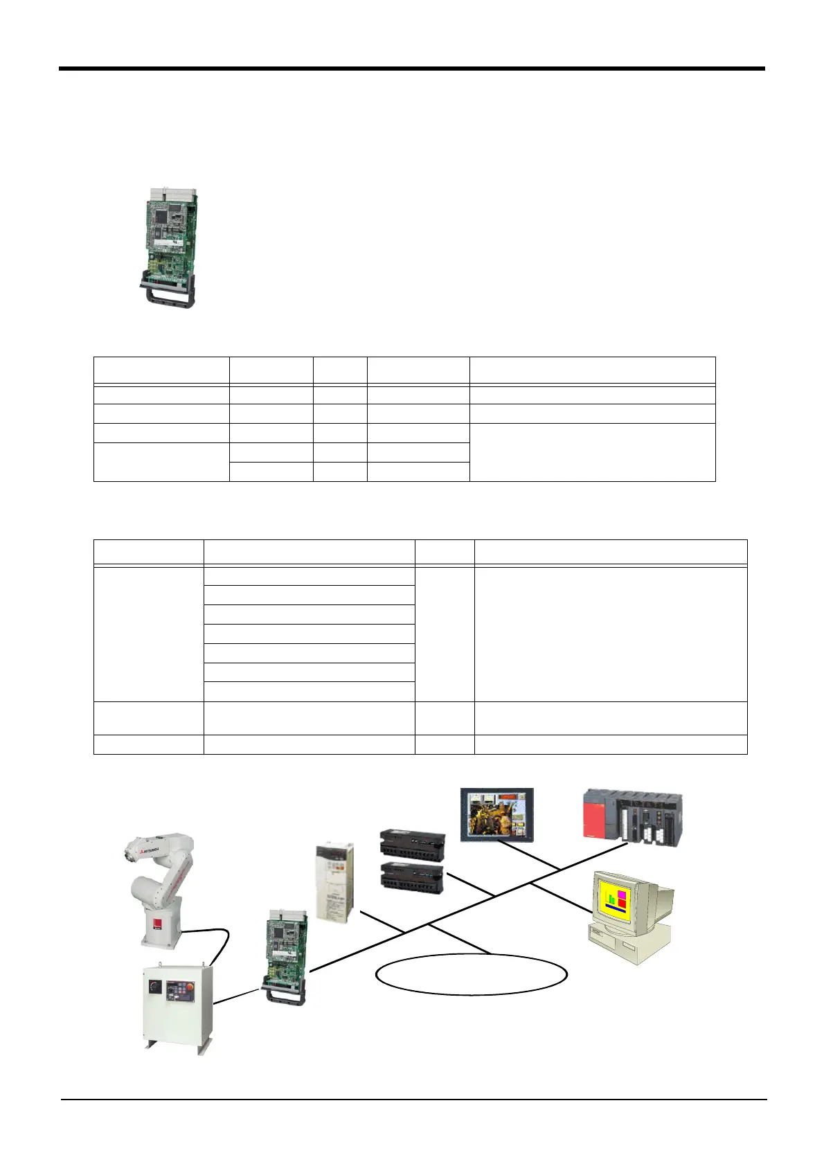
Fig.3-32 : Example of CC-Link Product Configuration
Part name Type Qty.
Mass(kg)
Note1)
Note1) Mass indicates one set.
Remarks
CC-Link interface 2D-TZ576 1 0.4
Manual BFP-A8701 1 -
Ferrite core E04SR301334 2 -
Be sure to install this for noise countermeasure.Cable clamp AL4 2 -
AL5 2 -
Part name Type Qty. Remarks
Master station
QJ61BT11(Q series)
1 FX series products are not supported.
QJ61BT11N(Q series)
AJ61QBT11(QnA series)
A1SJ61QBT11(QnAS series)
AJ61BT11(A series)
A1SJ61BT11(AnS series)
A80BD-J61BT11(personal computer board)
Communication cable - 1
Shielded 3-core twisted cable
This cable may be manufactured by the customer.
Terminal resistor - 1 110Ω or 130Ω is recommended.
Cc-Link interface
(this option)
Partner manufacturers' devices
I/O unit
Display
Sequencer
Robot arm
Controller
Personal computer
Inverter
Controller (Example of CR3D-700)
 Loading...


