1 General configuration
1-4
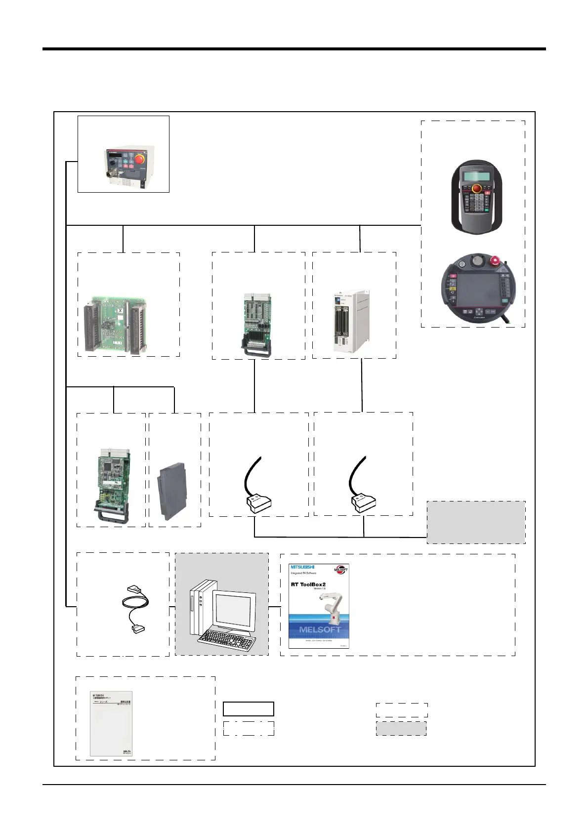
1.6.2 Controller
The devices shown below can be installed on the controller.
The controllers that can be connected differ depending on the specification of the robot.
Fig.1-2 : Structural equipment
Personal computer
Prepared by customer
Standard configuration
Options
Prepared by customer
[Caution]
The photograph is the image figure.
equipment
Special specifications
Instruction Manua l(printed)
・ 5S-DJ00-PE01
CC-Link
interface
2D-TZ576
Extension
memory
cassette
2D-TZ454
Parallel I/O unit
2A-RZ361(Sink)/
2A-RZ371
(Source)
External I/O cable
・ 2D-CBL05 (5m)
・ 2D-CBL15 (15m)
PLC(Programmable
Logic Controller)
External device
Prepared by customer
Teaching pendant
(T/B)
R32TB
R56TB
Parallel I/O interface
2D-TZ368(Sink)/
2D-TZ378
(Source)
External I/O cable
・ 2A-CBL05 (5m)
・ 2A-CBL15 (15m)
Personal computer
cable
2D-232CBL03M
(RS-232)
*)Refer to Table 1-4 for
USB cable
Controller
CR1DA-700 series
RT Tool Box2
(MS-Windows2000/XP/Vista)
・3D-11C-WINJ(CD-ROM)
RT Tool Box2 mini
(MS-Windows2000/XP/Vista)
・ 3D-12C-WINJ(CD-ROM)
*1) Corresponding to the sink
or source to be used, set
-
ting of the controller is nec
-
essary.
Pneumatic hand interface
2A-RZ365(Sink)/
2A-RZ375(Source)
*1)
 Loading...


