6Safety
Safety 6-108
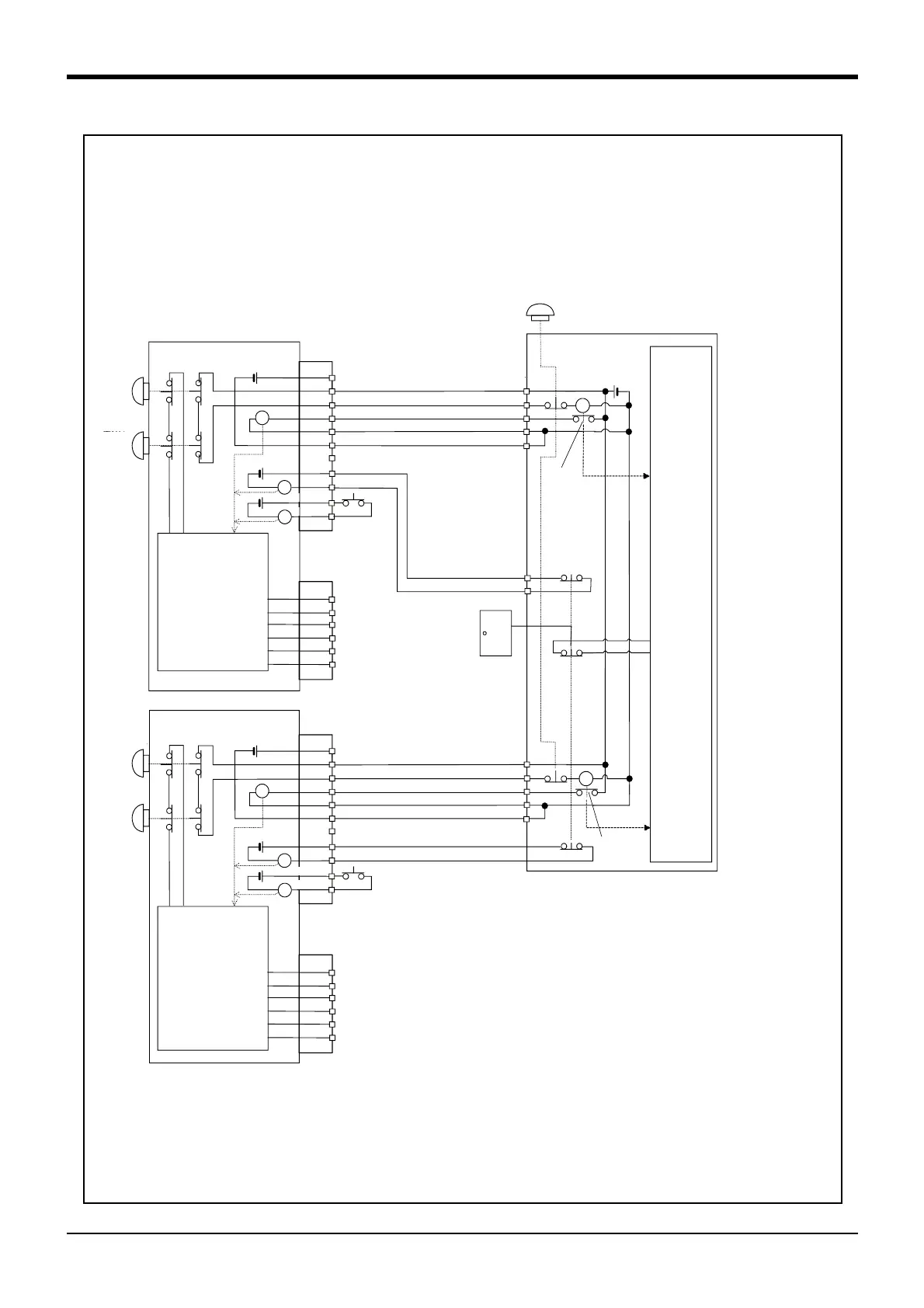
Fig.6-4 : Example of safety measures (Wiring example 4)
周辺装置
の非常停止
出力
周辺装置内部
非常停止回路
周辺装置
監視
RA
1A/1B
2A/2B
3A/3B
4A/4B
5A/5B
6A/6B
8A/8B
9A/9B
1A/1B
2A/2B
3A/3B
4A/4B
5A/5B
6A/6B
EMGIN1/2
EMGOUT1/2
内部非常停止回路
ロボットコントローラ #
1
TB非常停止
ボタン
OP非常停止
ボタン
}
RA
RA
RA
7A/7B
}
}
10A/10B
11A/11B
未接続
付加軸用コンタクタ
コントロール出力
エラー出力
モード出力
非常停止スイッチ
(4接点タイプ)
ドアスイッチ入力
イネーブリング
デバイス
安全柵のドア
ドアスイッチ出力
監視
1A/1B
2A/2B
3A/3B
4A/4B
5A/5B
6A/6B
8A/8B
9A/9B
1A/1B
2A/2B
3A/3B
4A/4B
5A/5B
6A/6B
EMGIN1/2
EMGOUT1/2
内部非常停止回路
ロボットコントローラ #
1
}
RA
RA
RA
7A/7B
}
}
10A/10B
11A/11B
未接続
付加軸用コンタクタ
コントロール出力
エラー出力
モード出力
ドアスイッチ入力
イネーブリング
デバイス
周辺装置
の非常停止
出力
監視
RA
TB非常停止
ボタン
OP非常停止
ボタン
ロボットコント
ローラ内電源
24V
ロボットコント
ローラ内電源
24V
周辺装置
側電源24V
<Wiring example 4>: Connect the emergency stop switch of peripheral equipment, and the door switch to two robot controllers,
and it interlocks. Connect the enabling device to the robot controller.The power supply for emergency stop
input uses the power supply of peripheral equipment. Monitor the emergency stop state by the peripheral
equipment side.
<Operation of the emergency stop>
If the emergency stop switch of peripheral equipment is pushed, the robot will also be in the emergency
stop state. And, if the emergency stop switch of OP or T/B is pushed in the state of the power of robot
controller OFF, peripheral equipment state can be the emergency stop also.
*1)
*2)
*7)
*2)
*4)
A-contact
*1)EMGIN1/2, and EMGOUT1/2 have the two terminals separately,
and show that they are the two lines. Always connect the two
lines.
If necessary to stop two robots simultaneously by one emergency
stop switch please use the 4 contact type emergency stop switch.
*2) 1A/1B, and 2A/2B terminal of EMGIN is short-circuited at factory
shipments. Remove it, and connect the emergency stop switch
and power supply of peripheral equipment. Connect the power
supply of peripheral equipment by the polarity shown in the figure.
*3)5A/5B, and 6A/6B terminal of EMGIN is short-circuited at factory
shipments. Remove it and connect with the power supply ground
of peripheral equipment.
Notes) Please use 5A/5B and 6A/6B terminal, connected.
*4) Please use a A contact type of the relay with the compulsive
guide.
*5) The emergency stop button of the robot controller operation panel.
*6) The emergency stop button of T/B connected to the robot controller.
*7) Emergency stop input relay.
*8) Refer to Page 55, "3.6.4 Enabling device function"for the enabling device.
*4)
A-contact
*7)
[Caution] Since we have omitted the information in part because of explanation, there is the section different from the
product. Also refer to Page 52, "Fig.3-13 : External emergency stop connection".
Robot controller #1
Robot controller #1
*5)
*6)
TB
Emer
-
gency
stop
button
OP
Emer
-
gency
stop
button
Power supply in the
robot controller 24V
Power supply in the
robot controller 24V
Not connected
Door switch input
Enabling
device
*8)
Error output
Mode output
Contactor control
output for addi
-
tional axes
Safety fence door
Power
supply24V
Monitor
Circuit
Monitor
Monitor
Peripheral equipment
Emergency stop switch
(4- contact type)
*1)
Not connected
Door switch input
Enabling
device
Error output
Mode output
Contactor control
output for addi
-
tional axes
*1)
*2)
*8)
*5)
*6)
TB
Emer
-
gency
stop
button
OP
Emer
-
gency
stop
button
Internal emergency
stop circuit
Internal emergency
stop circuit
*3)
*3)
 Loading...


