2 Robot arm
Outside dimensions ・ Operating range diagram 2-14
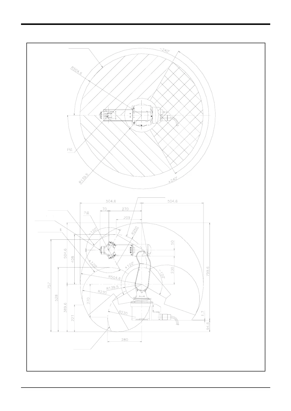
(3) Operating range (Common to the standard/CE Marking)
Fig.2-5 : Operating range diagram (Common to the standard/CE Marking)
注)側面図の姿勢
各軸の角度が J1=0°,J2=0°,J3=90°,J4=0°,J5=0°,J6=0°の場合を図示しています。
注)動作範囲制限
J1軸が (-75°< J1 < 70°)で,かつJ2軸が (J2 < -110°)の範囲にある時,J3軸は (80°<= J3)に制限されます。
P-point path
Flange downward limit line
P-point path
Control point
(R-point)
Flange upward
limit line
Flange downward
singular point limit
Note) The posture of side view
The case where the angle of each axis is the following is shown
J1=0 degree, J2=0 degree, J3=90 degree, J4=0 degree, J5=0
degree., J6=0 degree.
Note) Restriction of operating range
If the angle of J1 axis is -75 degree < J1 < 70 degree and J2
axis is J2 < -110 degree, the operating range of J3 axis is lim
-
ited to 80 degree <= J3.
 Loading...


