3 Controller
Parallel I/O interface 3-70
■ Connector pin No. and signal assignment
The station number is fixed by the slot to install and the allocation range of the general-purpose input-and-
output signal is fixed.
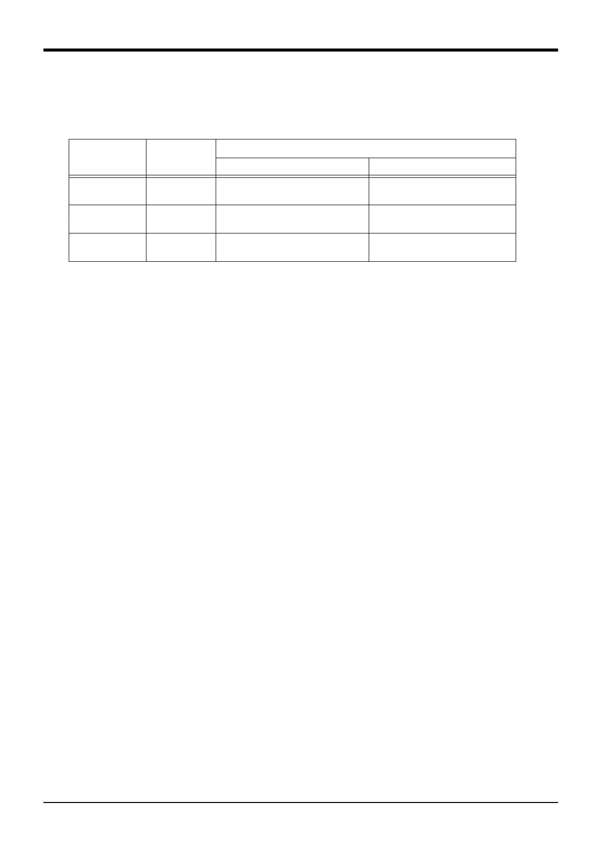
Table 3-14 : The slot number and the station number
The connector pin number of the parallel input-and-output interface installed in SLOT1 and signal number
allocation are shown in Table 3-15 and Table 3-16.
Slot
number
Note1)
Note1) In case of the CR1DA controller, the available slot is only SLOT1.
Station
number
Range of the general-purpose input-and-output signal
Connector <1> Connector <2>
SLOT1 0 Input : 0 to 15
Output : 0 to 15
Input : 16 to 31
Output : 16 to 31
SLOT2 1 Input : 32 to 47
Output : 32 to 47
Input : 48 to 63
Output : 48 to 63
SLOT3 2 Input : 64 to 79
Output : 64 to 79
Input : 80 to 95
Output : 80 to 95
 Loading...


