4 INTELLIGENT COMMUNICATION MODULE REPLACEMENT
4 - 13
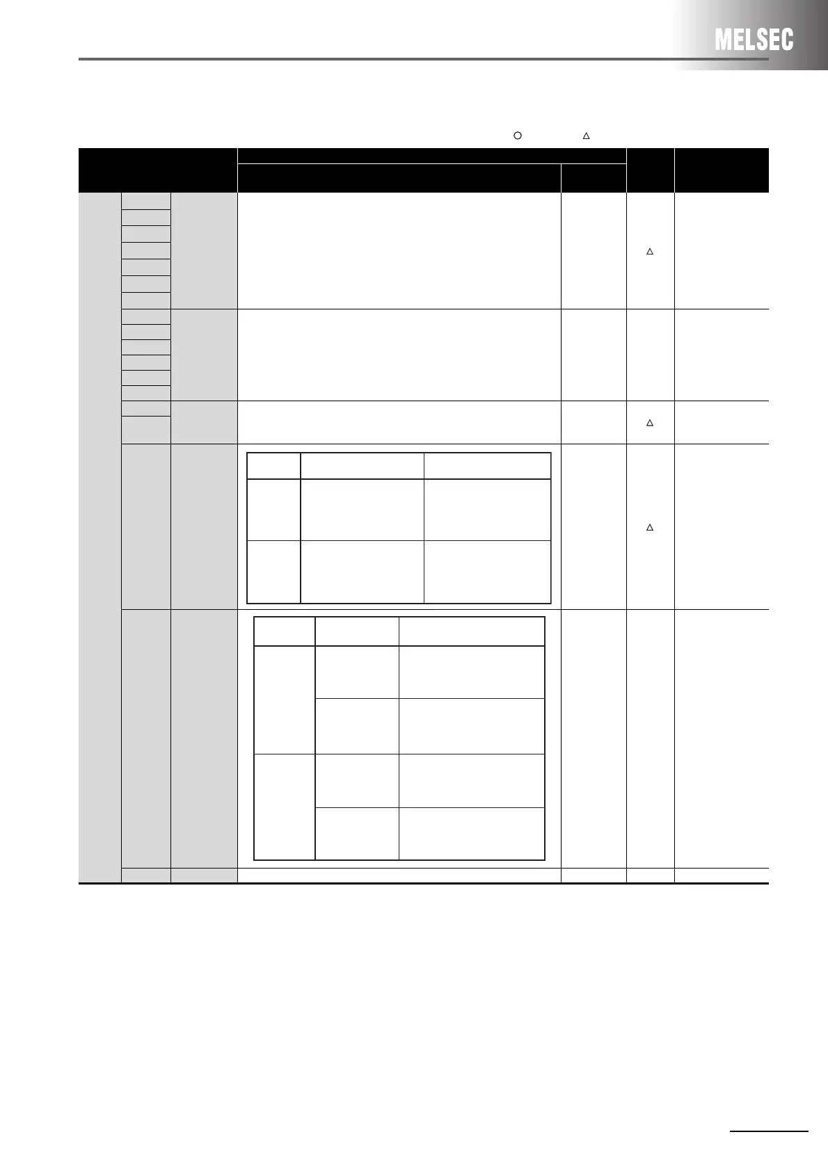
(3) Replacement of intelligent communication module AD51-S3
: Compatible, : Partial change required, ×: Incompatible
Switch name
Specifications
Compat-
ibility
Precautions for
replacement
AD51-S3
QD51
QD51-R24
DIP
switch
SW1
Memory
protect range
48K bytes of the RAM area may be used for memory protect setting in
units of 8K bytes.
The system data area may also be used for the setting.
*1
-
The write protect
setting of a flash
ROM is available.
Set the switches in
the GX Developer’s
PLC parameter
settings.
SW2
SW3
SW4
SW5
SW6
SW7
SW8
- Fixed to OFF - -
SW9
SW10
SW11
SW12
SW13
SW14
Terminal
resistor
SW14 and SW15 are both OFF: Without terminal resistor
SW14 and SW15 are both ON: With terminal resistor
-
Connect the
included terminal
resistor.
SW15
SW16
Console
channel
-
Set the switches in
the GX Developer’s
PLC parameter
settings.
SW17
System data
transfer
--
For AD51H-BASIC,
the system data is
not needed.
SW18 - Fixed to OFF - -
ON
OFF
GPP/HGP/PHP
VG-670/A6GPP
General port
General port
SW16
Position
CHI
(RS-422)
CH3
(RS-232C)
System data is transferred from
channel 1 addresses 8000
H to
80FF
H to system data area,4F00H
to 4FFF
H.
ON
OFF
Specific pattern
Specific pattern
Unspecific pattern
Unspecific pattern
SW17
Position
Description
8000
H to 8004H
Data
Not transferred.
Not transferred.
Not transferred.
 Loading...


