3 ETHERNET INTERFACE MODULE REPLACEMENT
3 - 25
The following shows a program example at transition from the A/AnS series to the Q series.
When applying the program example introduced in this section to an actual program,
sufficiently study if there will be any problem in control on the target system.
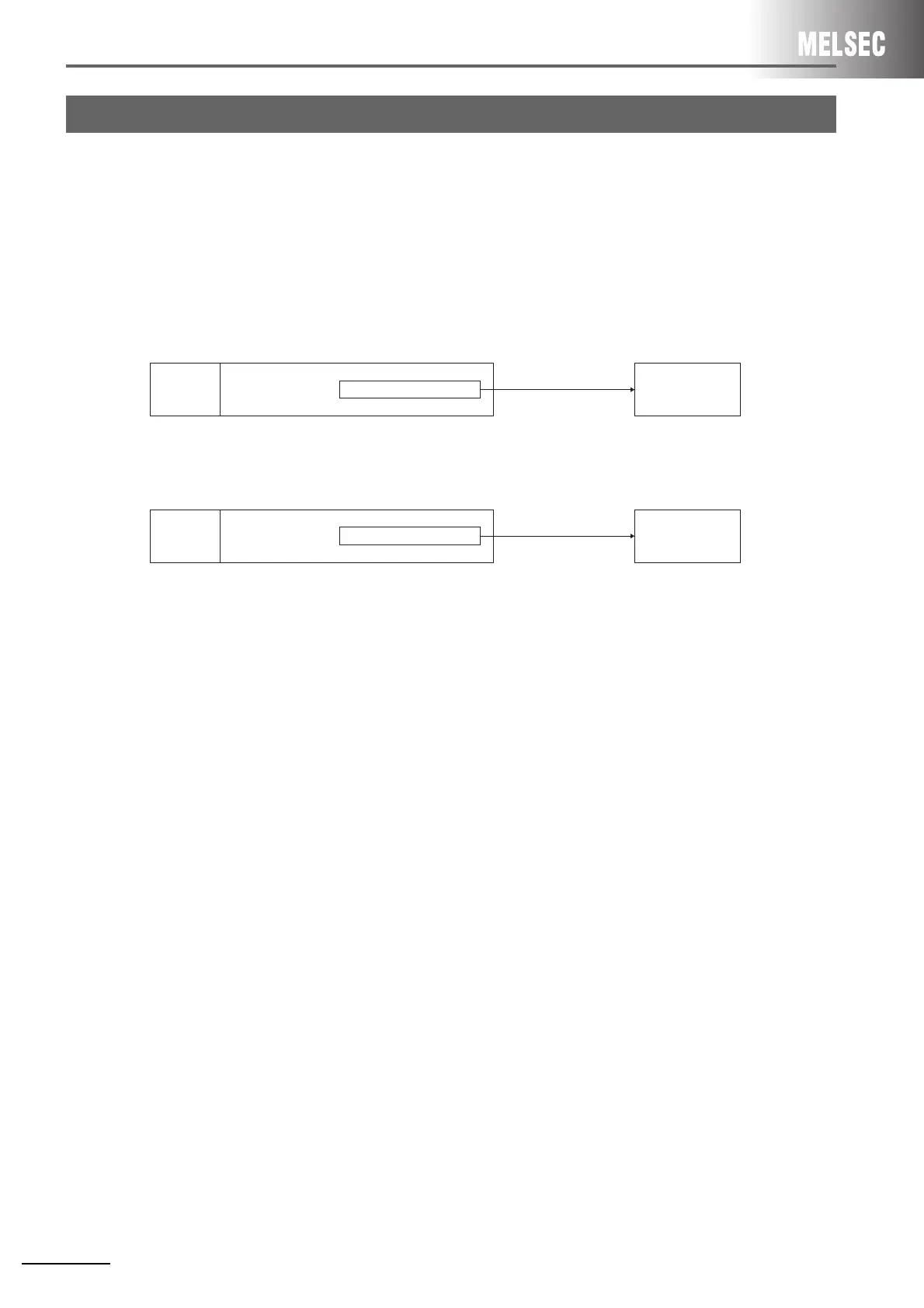
(1) System configuration
The following shows the system configuration used in the program example in this section.
(a) A/AnS series
(b) Q series
*1 The Ethernet interface module is mounted on slot 0 of the base module.
The I/O signals of the Ethernet interface module shall be X/Y0 to X/YF.
3.9 Program Examples
Ethernet interface module
*1
For connection No.1
fixed buffer transmission
External device
A3UCPU
Transmission request
signal (Y0)
Ethernet interface module
*1
For connection No.1
fixed buffer transmission
External device
Q25HCPU
BUFSND instruction
 Loading...


