2 SERIAL COMMUNICATION MODULE REPLACEMENT
2 - 17
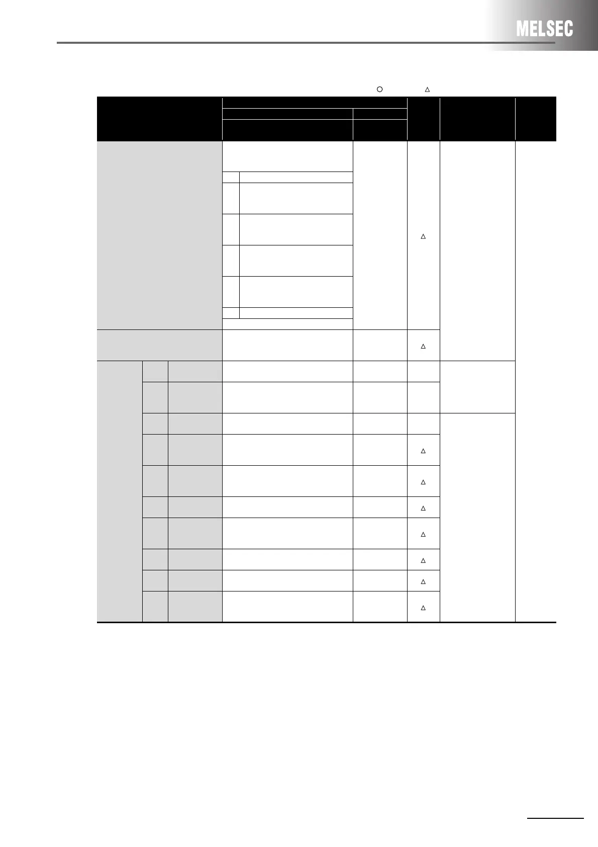
(b) A1SJ71UC24-R4
:Compatible, :Partial change required, ×:Incompatible
*1 When the A1SJ71UC24-R4 is mounted to the A1ADP-SP
When the A1SJ71UC24-R4 with the software version X or later, the A1ADP-SP setting can be used.
This setting is used to create a sequence program in the non-procedural mode by using the dedicated instructions for the
computer link function in the AnACPU.
When using the dedicated instructions for the computer link module, switch the A1ADP-SP setting to ON. When not using
them, switch the setting to OFF.
When the A1SJ71UC24-R4 with the software version W or earlier is used, the dedicated instructions for the computer link
function cannot be used.
Create a sequence program using the FROM/TO instructions.
Switch name
Description
Compat-
ibility
Precautions for
replacement
Reference
section
AnS series Q series
A1SJ71UC24-R4
QJ71C24N
QJ71C24N-R4
Mode switch
Each of the interface modes’ setting is
determined by the data communication
function to be used.
-
Set the switch settings
in the GX Developer
PLC parameter
settings.
Refer to Section 2.4
(3)
*1
.
Section 2.7
RS-422/485 (CH2)
0
to
3
Use not allowed
4
Non-procedural mode
or
bidirectional mode
5
to
8
Dedicated protocol (format1 to 4)
9
to
E
Use not allowed
F Self-loopback test
Station number switch
The station number of the module for
when date communications is performed
using dedicated protocol is set.
-
Transmission
specification
switch
SW01
master/local
station setting
The station type for use of multidrop link
function is set.
--
There is no multidrop
link function provided
for the Q series.
SW02
computer link/
multidrop link
selection
The function of computer link module to
be used is set.
--
SW03
A1ADP-SP
setting
--
Set the switch settings
in the GX Developer
PLC parameter
settings.
Refer to Section 2.4
(3)
*1
.
SW04
Write during
RUN enable/
disable setting
Write during RUN enable/disable in
dedicated protocol data communications
is set.
-
SW05
to
SW07
Transmission
speed setting
The transmission speed for when data is
to be transmitted/received is set.
-
SW08 Data bit setting
The data bit length of the data to be
transmitted/received is set.
-
SW09
Parity bit
enable/disable
setting
The parity bit ON/OFF of the data to be
sent/received is set.
-
SW10
Even/odd parity
setting
The type of parity bit to add to the data to
be transmitted/received is set.
-
SW11
Stop
bit setting
The stop bit length of the data to be
transmitted/received is set.
-
SW12
Sum check
enable/disable
setting
The sum check code presence in
dedicated protocol data communications
is set.
-
 Loading...


