2 SERIAL COMMUNICATION MODULE REPLACEMENT
2 - 24
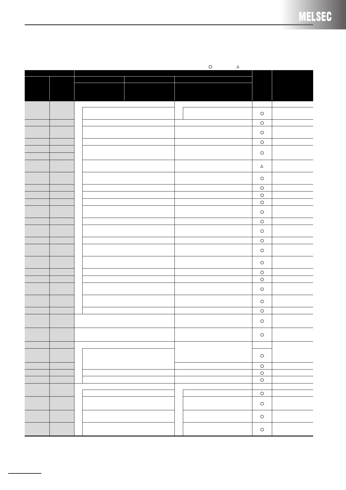
(2) Comparison between QnA/QnAS series and Q series
The table below shows the main assignment areas for the initial settings and for transmission/reception.
:Compatible, :Partial change required, ×:Incompatible
Buffer memory address Buffer memory name
Compat-
ibility
Precautions for
replacement
HEX DEC
QnA series QnAS series Q series
AJ71QC24N
AJ71QC24N-R2
AJ71QC24N-R4
A1SJ71QC24N1
A1SJ71QC24N1-R2
QJ71C24N
QJ71C24N-R2
QJ71C24N-R4
0
H
0
System setting area LED, communication error clear area -
CH1 LED OFF, communication error clear request
area
CH1 LED OFF, communication error
clear request area
to to to to
2E
H
to 38
H
46 to 56
Modem Function area
(For initial setting)
Modem function specification-1 area
(For initial setting)
39
H
to 8F
H
57 to 143 System area (use prohibited) System area (use prohibited)
90
H
, 130
H
144, 304
Mode switching area Mode switching specification area
91
H
, 131
H
145, 305
92
H
, 132
H
146, 306 System area (use prohibited) RS•DTR signal status spefication area
Use the default
value.
93
H
, 133
H
147, 307
DTR/DSR, DC control
specification area
DTR/DSR, DC control
specification area
94
H
, 134
H
148, 308 DC1/DC3 code specification area DC1/DC3 code specification area
95
H
, 135
H
149, 309 DC2/DC4 code specification area DC2/DC4 code specification area
96
H
, 136
H
150, 310 Word/byte specification area Word/byte specification area
97
H
, 137
H
151, 311
RS-232
CD terminal check setting area
RS-232
CD terminal check setting area
to to to to
A0
H
, 140
H
160, 320
On-demand buffer memory head address
specification area
On-demand buffer memory head address
specification area
A1
H
, 141
H
161, 321 On-demand data length specification area On-demand data length specification area
A2
H
, 142
H
162, 322
Send buffer memory
head address specification area
Send buffer memory
head address specification area
A3
H
, 143
H
163, 323 Send buffer memory length specification area
Send buffer memory length specification
area
A4
H
, 144
H
164, 324 Receive end data count specification area Receive end data count specification area
A5
H
, 145
H
165, 325 Receive end code specification area Receive end code specification area
A6
H
, 146
H
166, 326
receive buffer memory head address specification
area
receive buffer memory head address
specification area
A7
H
, 147
H
167, 327 receive buffer memory length specification area
receive buffer memory length
specification area
to to to to
200
H
to
220
H
512 to 544 System information area System information area
221
H
to
23D
H
545 to 573 Modem function area Modem function area
23E
H
574 System information area
System area (use prohibited)
-
23F
H
to
24E
H
575 to 590
System area (use prohibited)
24F
H
591 station No. setting check area
to to to to
3FF
H
1023 System area (use prohibited) System area (use prohibited)
400
H
1024
CH1 transfer buffer memory CH1 transfer buffer memory -
Send data count specification area Send data count specification area
401
H
to
5FF
H
1025 to
1535
Send data specification area Send data specification area
600
H
1536
Receive data count
specification area
Receive data count
specification area
601
H
to
7FF
H
1537 to
2047
Receive data storage area Receive data storage area
(Continued on next page)
 Loading...


