3 ETHERNET INTERFACE MODULE REPLACEMENT
3 - 20
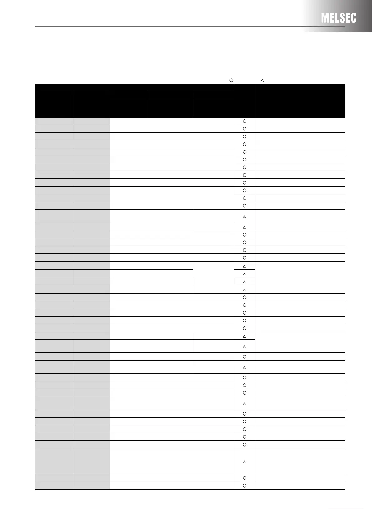
(2) Comparison between QnA/QnAS series and Q series
The buffer memory assignment of the QnA/QnAS series is compatible with that of the Q series.
The sequence program of the QnA/QnAS series can be used as is.
: Compatible, : Partial change required, ×: Incompatible
Buffer memory address Buffer memory name
Compat-
ibility
Precautions for replacement
HEX DEC
QnA series QnAS series Q series
AJ71QE71N3-T
AJ71QE71N-B5
AJ71QE71N-B2
A1SJ71QE71N3-T
A1SJ71QE71N-B5
A1SJ71QE71N-B2
QJ71E71-100
QJ71E71-B5
QJ71E71-B2
0 to 1
H
0 to 1 Local station IP address
2 to 3
H
2 to 3 System area (Use prohibited)
4
H
4 Special function setting
5 to A
H
5 to 10 System area (Use prohibited)
B to13
H
11 to 19 Monitoring timer
14
H
20 Automatically open UDP port No.
15 to 1D
H
21 to 29 System area (Use prohibited)
1E
H
30 TCP Maximum Segment transmission setting
1F
H
31 System area (Use prohibited)
20 to 27
H
32 to 39 Application setting area (Connection No.1 to 8)
28 to 5F
H
40 to 95 Exchange address settings area (Connection No.1 to 8)
60 to 66
H
96 to 102 System area (Use prohibited)
67
H
103
Communication specification during
STOP
System area
(Use prohibited)
Delete the sequence program.
68
H
104
E
2
PROM parameter portion specification
69
H
105 Initial error code
6A to 6B
H
106 to 107 Local station IP address
6C to 6E
H
108 to 110 Local station Ethernet address
6F
H
111 System area
70
H
112
E
2
PROM register status
System area
(Use prohibited)
Delete the sequence program.
71
H
113 Parameter use status
72
H
114
E
2
PROM read result
73
H
115
E
2
PROM write result
74
H
116 Automatically open UDP port No.
75
H
117 System area (Use prohibited)
76
H
118 Network No./Station No.
77
H
119 Group No.
78 to C7
H
120 to 199 Information for each connection (Connection No.1 to 8)
C8
H
200 LED ON status (Left side) LED ON status
Check the LED ON status at C8
H
(200).
C9
H
201 LED ON status (Right side)
Hub connection
status area
CA
H
202 Operation mode setting switch status
CB
H
203 Exchange condition setting switch status
GX Developer
setting status
Stores the setting status of the GX Developer
network parameters.
CC
H
204 System area (Use prohibited)
CD
H
205 RECV instruction execution request
CE
H
206 System area (Use prohibited)
CF to DF
H
207 to 223 Data link command execution result by channel
Stores the execution result of the ZNRD,
ZNWR instructions.
E0 to E2
H
224 to 226 System area (Use prohibited)
E3
H
227 No. of errors generated
E4
H
228 Error log write pointer
E5 to 174
H
229 to 372 Error log block 1 to 16
175 to 177
H
373 to 375 System area (Use prohibited)
178 to 1FF
H
376 to 511 Status information by protocol type
Some assignments differ.
For details, refer to the Q Corresponding
Ethernet Interface Module User's Manual
(Basic).
200 to 201
H
512 to 513 Subnet mask field
202 to 203
H
514 to 515 Default router IP address
 Loading...


