4 INTELLIGENT COMMUNICATION MODULE REPLACEMENT
4 - 9
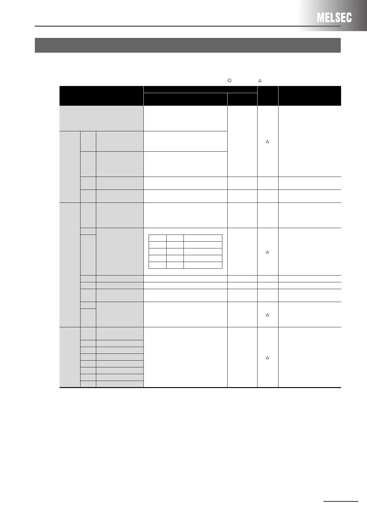
(1) Replacement of intelligent communication module AD51H-S3
: Compatible, : Partial change required, ×: Incompatible
*1 The next page shows the settings of mode setting switch 2 that vary by the combination of devices to be used as consoles
and debuggers.
4.4 Switch Setting
Switch name
Specifications
Compat-
ibility
Precautions for replacement
AD51H-S3
QD51
QD51-R24
Mode setting switch 1
0 or 1: Execution mode
2 or 3: Multitask debugging mode
4: Programming
5 to F: Unusable
-
Set the switches in the GX
Developer’s PLC parameter
settings.
Mode
setting
switch 2
SW1
Console or debug port
setting
Set by the combination of devices to be
used as a console and a debugger.
*1
to
SW5
SW6
BASIC program
operation stop by
[BREAK]/[Ctrl] + [C]
keys.
OFF: Disabled
ON: Enabled
SW7
Boot target of
execution program
OFF: Memory card priority
ON: EP-ROM priority
--
Execution programs are stored
in a flash ROM.
SW8 Scheduled time of task
OFF: 50ms
ON: 100ms
--
The scheduled time of task
must be fixed to 50ms.
Switch 2
SW1
Operation of the
AD51H when resetting
a programmable
controller CPU
OFF: Reset signal invalid
ON: Reset signal valid
--
The reset signal of
programmable controller CPU
is valid.
SW2
Time accessible by
FROM/TO instructions
from a programmable
controller CPU when
resetting the AD51H
-
Set the switches in the GX
Developer’s PLC parameter
settings.
(Select 200ms or 2000ms.)
SW3
SW2 SW3 Accessible time
OFF OFF 200 ms
OFF ON 500 ms
ON OFF 1000 ms
ON ON 2000 ms
SW4 - Fixed to OFF - -
SW5 - Fixed to OFF - -
SW6
EP-ROM type to be
used
OFF: 64kROM/128kROM
ON: 256kROM
--No EP-ROM
SW7
Terminal resistor
setting
SW7 and SW8 are both OFF: Without
terminal resistor
SW7 and SW8 are both ON: With terminal
resistor
-
Connect the included terminal
resistor.
SW8
Memory-
protect
range
switch
SW1
Memory-protect range
0 to 0FFFFh
OFF: Not protected
ON: Protected
-
The write protect setting of a
flash ROM is available.
Set the switches in the GX
Developer’s PLC parameter
settings.
SW2 10000 to 1FFFFh
SW3 20000 to 2FFFFh
SW4 30000 to 3FFFFh
SW5 40000 to 4FFFFh
SW6 50000 to 5FFFFh
SW7 60000 to 6FFFFh
SW8 70000 to 7FFFFh
 Loading...


