4 INTELLIGENT COMMUNICATION MODULE REPLACEMENT
4 - 11
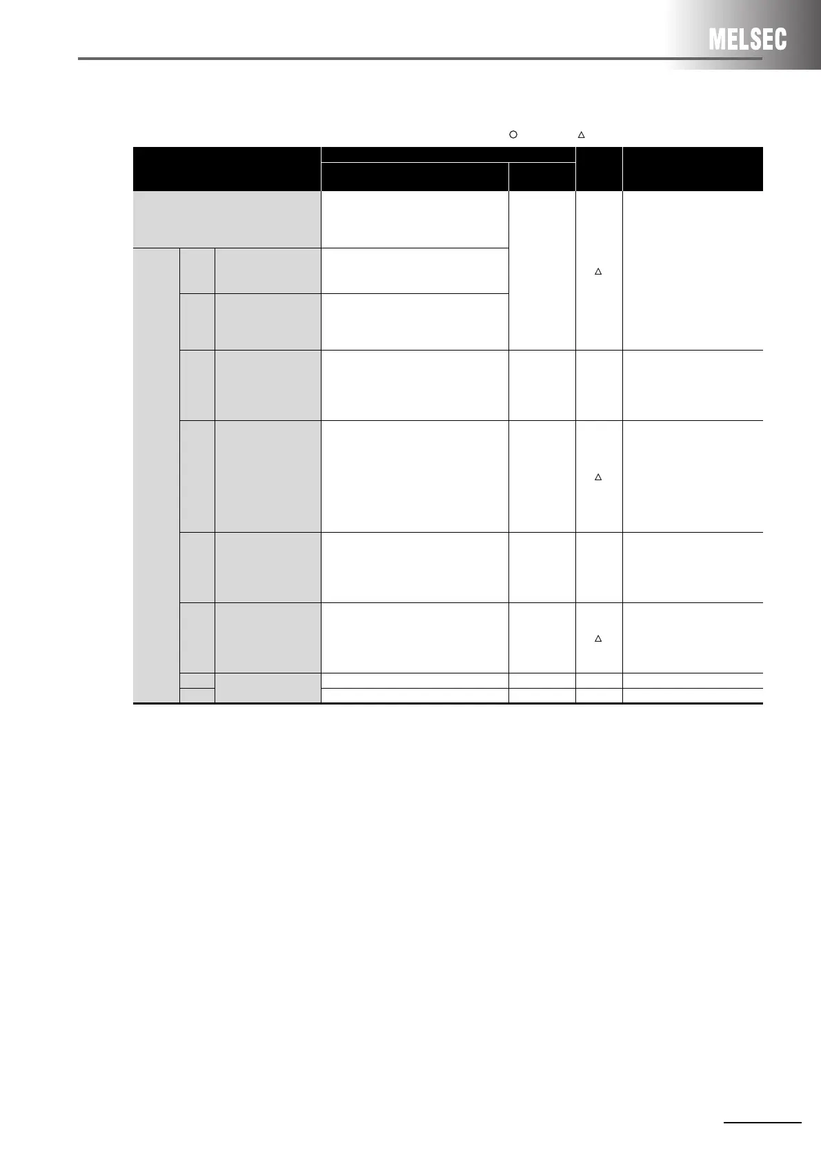
(2) Replacement of intelligent communication module A1SD51S
: Compatible, : Partial change required, ×: Incompatible
*1 The next page shows the settings of mode setting switch 2 that vary by the combination of devices to be used as consoles
and debuggers.
Switch name
Specifications
Compat-
ibility
Precautions for replacement
A1SD51S
QD51
QD51-R24
Mode setting switch 1
0 or 1: Execution mode
2 or 3: Multitask debugging mode
4: Programming
5 to F: Unusable
-
Set the switches in the GX
Developer’s PLC parameter
settings.
Mode
setting
switch 2
SW1
Console or debug port
setting
Set by the combination of devices to be
used as a console and a debugger.
*1
to
SW5
SW6
BASIC program
operation stop by
[BREAK]/[Ctrl] + [C]
keys.
OFF: Disabled
ON: Enabled
SW7
Operation of the
A1SD51S when the
programmable
controller CPU is reset
Set the reset signal from the
programmable controller CPU to valid or
invalid.
OFF: Reset signal invalid
ON: Reset signal valid
--
There is no setting of valid or
invalid.
The reset signal of the
programmable controller CPU
is valid.
SW8
The time for how long
the programmable
controller CPU can
access to the
A1SD51S using the
FROM/TO instructions
after the A1SD51S is
reset
OFF: 200ms
ON: 2000ms
-
Set the switches in the GX
Developer’s PLC parameter
settings.
(Select 200ms or 2000ms.)
SW9
Backup area clear
setting
OFF: Clear disabled
ON: Clear enabled
-×
Common memory is not backed
up by a battery. To save data,
use the file register or latch
device of the programmable
controller CPU.
SW10
E
2
PROM write protect
setting
OFF: Write protection OFF
ON: Write protection ON
-
Write protect can be set for a
flash ROM.
Set the switches in the GX
Developer’s PLC parameter
settings.
SW11
(Not used)
---
SW12 - - -
 Loading...


