3. SIGNALS AND WIRING
3 - 60
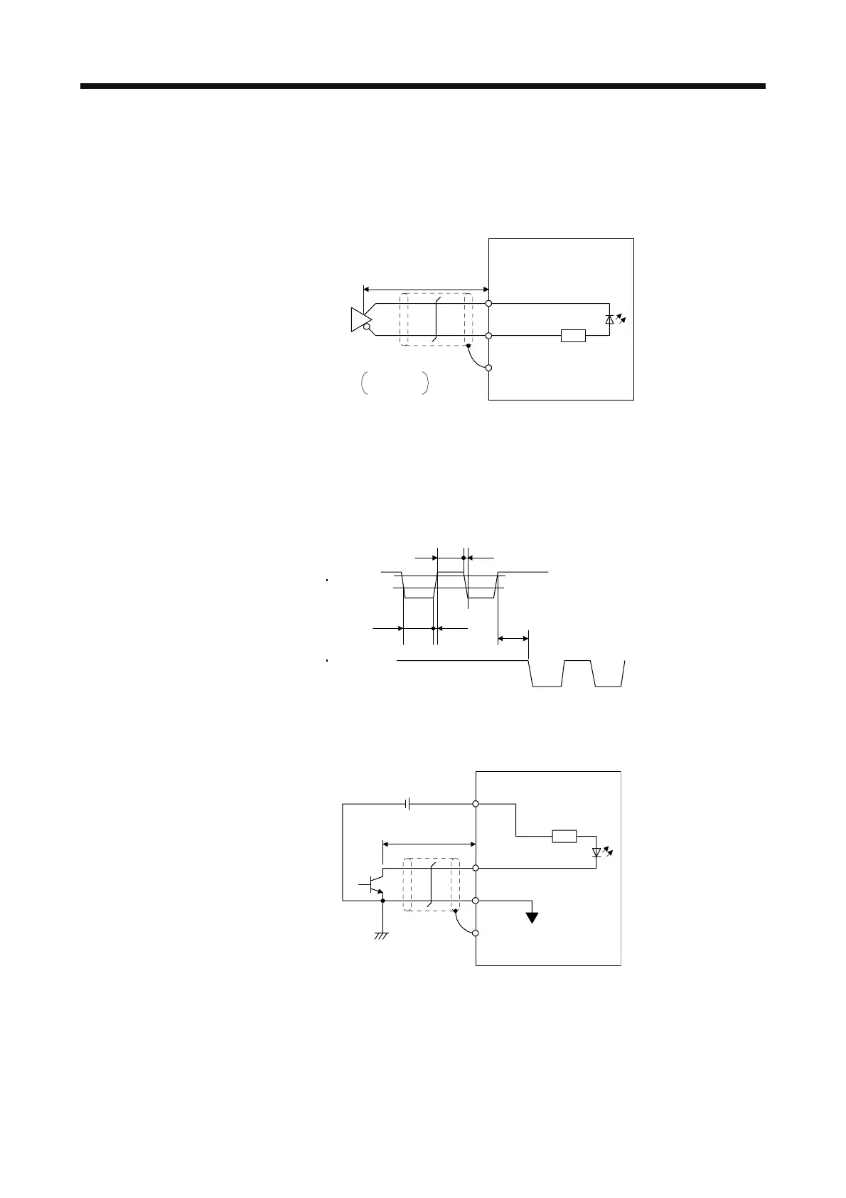
(3) Pulse train input interface DI-2
Give a pulse train signal in the differential line driver type or open-collector type.
(a) Differential line driver type
1) Interface
SD
PG (NG)
PP (NP)
Max. input pulse
frequency 4 Mpulses/s
(Note 2)
Servo amplifie
Am26LS31 or equivalent
Approximalely
100 Ω
V
OH
: 2.5 V
V
OL
: 0.5 VV
(Note 1)
10 m or less
Note 1. Pulse train input interface is comprised of a photocoupler.
If a resistor is connected to the pulse train signal line, it may malfunction due to
reduction in current.
2. When the input pulse frequency is 4 Mpulses/s, set [Pr. PA13] to "_ 0 _ _".
2) Input pulse condition
0.9
0.1
tc tLH
tc tHL
tF
PP PG
NP NG
tLH = tHL < 50 ns
tc > 75 ns
tF > 3 µs
(b) Open-collector type
1) Interface
Approximately
1.2 kΩ
Servo amplifie
24 V DC
OPC
PP, NP
DOCOM
SD
Max. input pulse
frequency 200 kpulses/s
2 m or less
(Note)
Note. Pulse train input interface is comprised of a photocoupler.
If a resistor is connected to the pulse train signal line, it may malfunction due to
reduction in current.
 Loading...
