11. OPTIONS AND AUXILIARY EQUIPMENT
11 - 31
(4) Cables
(a) Cables for the brake unit
For the brake unit, HIV cable (600 V grade heat-resistant PVC insulated wire) is recommended.
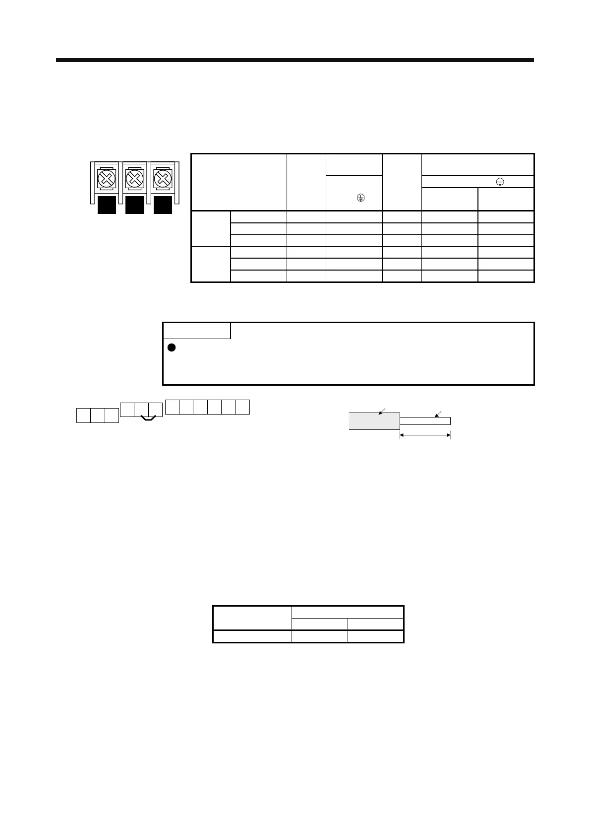
1) Main circuit terminal
Crimp
terminal
Wire size
N/-, P/+, PR,
Brake unit
Main
circuit
terminal
screw
size
N/-, P/+,
PR,
Tightening
torque
[N•m]
HIV wire
[mm
2
]
AWG
FR-BU2-15K M4 5.5-4 1.5 3.5 12
FR-BU2-30K M5 5.5-5 2.5 5.5 10
N/- P/+ PR
Terminal block
200 V
class
FR-BU2-55K M6 14-6 4.4 14 6
FR-BU2-H30K M4 5.5-4 1.5 3.5 12
FR-BU2-H55K M5 5.5-5 2.5 5.5 10
400 V
class
FR-BU2-H75K M6 14-6 4.4 14 6
2) Control circuit terminal
POINT
Under tightening can cause a cable disconnection or malfunction. Over
tightening can cause a short circuit or malfunction due to damage to the screw
or the brake unit.
A
RES
PC
B
SD
BUE
C
MSG
SD
MSG
SD SD
Jumper
Terminal block
Insulato
Core
6 mm
Wire the stripped cable after twisting to prevent the cable
from becoming loose. In addition, do not solder it.
Screw size: M3
Tightening torque: 0.5 N•m to 0.6 N•m
Wire size: 0.3 mm
2
to 0.75 mm
2
Screw driver: Small flat-blade screw driver
(Tip thickness: 0.4 mm/Tip width 2.5 mm)
(b) Cables for connecting the servo amplifier and a distribution terminal block when connecting two sets
of the brake unit
Wire size
Brake unit
HIV wire [mm
2
]AWG
FR-BU2-15K 8 8
 Loading...

