3. SIGNALS AND WIRING
3 - 33
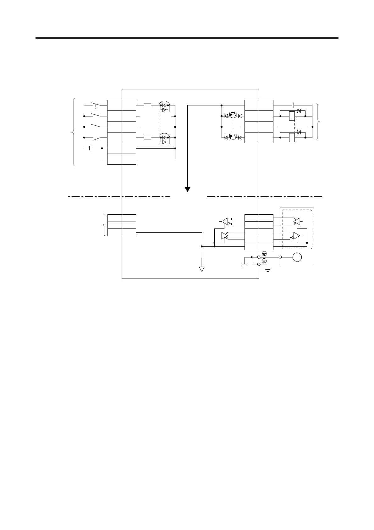
3.8 Interfaces
3.8.1 Internal connection diagram
Approximately
6.2 kΩ
Encoder
3
2
4
7
8
MR
MRR
MD
MDR
LG
PE
Servo motor
M
CN2
EM2
CN3
20
2
12
19
10
5
CN3
3
13
9
15
DOCOM
Servo amplifie
USB
D+
GND
D- 2
3
5
CN5
MBR
DICOM
DICOM
(Note 1)
Forced stop 2
(Note 1)
Approximately
6.2 kΩ
RA
RA
Isolated
(Note 2)
24 V DC
(Note 2)
24 V DC
(Note 3)
(Note 3)
(Note 3)
(Note 3)
(Note 3)
Note 1. This diagram shows sink I/O interface. For source I/O interface, refer to section 3.8.3.
2. The illustration of the 24 V DC power supply is divided between input signal and output signal for convenience. However, they
can be configured by one.
3. The CN3-2, CN3-9, CN3-12, CN3-15, and CN3-19 pins are available with servo amplifiers having software version C5 or later,
and manufactured in May 2016 or later. For the servo amplifiers manufactured in China, these pins have been available from
the June 2016 production.
 Loading...
