7 - 27 7 - 27
MELSEC-Q
7 PARAMETER SETTING
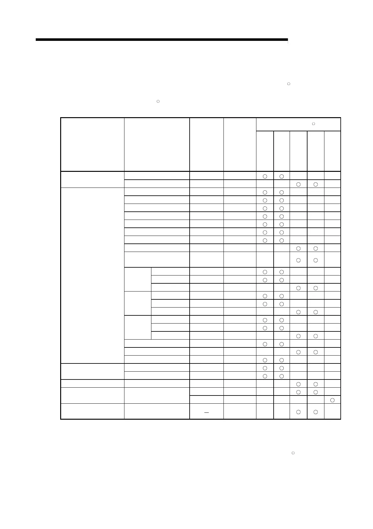
(1) Device codes
(a) Set the device codes for the programmable controller CPU devices and
QJ71MT91 buffer memory area assigned to the MODBUS
R
devices.
(b) The device codes have different setting ranges depending on the
MODBUS
R
devices.
Refer to the following table for the device code setting ranges.
Assignable MODBUS
R
Device
Classification Device Name
Device
Symbol
Device
Code(*5)
Coil
Input
Input register
Holding register
Extended file
register
Special relay SM(*3) 0091H
Internal system device
Special register SD(*3) 00A9
H
Input X(*3) 009CH
Output Y(*3) 009DH
Internal relay M(*3) 0090H
Latch relay L 0092H
Annunciator F 0093H
Edge relay V 0094H
Link relay B(*3)(*4) 00A0H
Data register D(*3)(*6) 00A8H
Link register
W(*3)(*4)
(*6)
00B4
H
Coil TC 00C0H
Contact TS 00C1H
Timer
Current value TN 00C2
H
Coil SC 00C6H
Contact SS 00C7H
Retentive
timer
Current value SN 00C8
H
Coil CC 00C3H
Contact CS 00C4H
Counter
Current value CN 00C5
H
Link special relay SB(*3) 00A1H
Link special register SW(*3) 00B5H
Internal user device
Step relay S 0098
H
Direct input DX 00A2H
Direct device
Direct output DY 00A3
H
Index register Index register Z 00CCH
R 00AFH
File register File register
ZR(*1) 00B0
H
QJ71MT91 buffer memory
(*2)(*3)
User free area
F000
H
*1: The device assigned to the extended file register is fixed to the file register (ZR).
Refer to Section 7.4.4 for the extended file register.
*2: Refer to Section 7.4.5 for device assignment to the QJ71MT91 buffer memory.
*3: Only this device is supported when the QJ71MT91 is mounted on a MELSECNET/H remote I/O
station. An error will occur if an access request is received from the MODBUS
R
/TCP master with
any other device assigned.
*4: Corresponds to LB and LW on a MELSECNET/H remote I/O station.
 Loading...


